ESP32 Bluetooth Controlled 10Ch HomeAutomation System Using Android App.

ESP32 Bluetooth Controlled 10Ch HomeAutomation System Using Android App.

We all know ESP32 comes with WIFI, Bluetooth Low Energy and Bluetooth Classic,

In this Homeautomation project, we are going to use ESP32 Bluetooth classic feature to control our homeappliances .

Components Requried

Coustom Made PCB.

Although we can make this project using esp32 and relay modules , but to look project more professional and compact, I used Coustom Designed PCB for this project and with this PCB, We are able to control total 10 no. of devices. 

Designing the PCB

To design the circuit and PCB, we used EasyEDA which is a browser based software to design PCBs.

Designing the circuit works like in any other circuit software tool, you place some components and you wire them together. Then, you assign each component to a footprint.

Having the parts assigned, place each component. When you’re happy with the layout, make all the connections and route your PCB.

Save your project and export the Gerber files.

Ordering the PCBs at PCBWay

This project is sponsored by PCBWay. PCBWay is a full feature Printed Circuit Board manufacturing service.

Turn your DIY breadboard circuits into professional PCBs – get 10 boards for approximately $5 + shipping (which will vary depending on your country).

Once you have your Gerber files, you can order the PCB. Follow the next steps.

1. Download the Gerber files – click here to download the .zip file.

2. Go to PCBWay website and open the PCB Instant Quote page. 

3. PCBWay can grab all the PCB details and automatically fills them for you. Use the “Quick-order PCB (Autofill parameters)”.

4. Press the “+ Add Gerber file” button to upload the provided Gerber files.

And that’s it. You can also use the OnlineGerberViewer to check if your PCB is looking as it should.

After approximately one week using the DHL shipping method, I received the PCBs at my place.As usual, everything comes well packed, and the PCBs are really high-quality. 

The letters on the silkscreen are really well-printed and easy to read. Additionally, the solder sticks easily to the pads.

PCBWay Year End Big Sale and Christmas Shopping Festival 2021.

PCBWay are now offering different sales offers and coupons at Christmas Festival 2021. I hope you will not miss the opportunity and avail of these offers as soon as possible. Since limited days are remaining. 

So let’s get started with PCBWay Year End Big Sale & Christmas Shopping Festival 2021.

The PCBWay is PCB producing company based in China and offers numerous services such as PCB with different types such as single layer PCB, double Layer PCB, multilayer PCB, etc, with that PCB prototyping services and PCBA.

Now regard Christmas they are providing different offers through using them you can get Free Christmas Coupons and Up to 52% Off for 3D Printing & CNC Machining.

Special Sales in PCBWay Store!

PCBWay has providing special sales in their store, using them you can get Up to 50% Off on different electronic modules like ESP32, ARDUINO BOARDS , IPS touch screen display, Robotic Arm etc

Lucky Draw.

With all these offers here & Coupons, One lucky draw is also conducted. To take part in this lucky draw the last date is December 31, 2021.

                                                           Rules.

1.Each PCBWayer (who had PCBWay shopping experience before) has TWO chances to draw the lottery. And ONE extra chance will be given if you place any order during December.

2.The beans would be automatically added into your account. You can use it to redeem modules in PCBWay store.

3.If you have any questions about how to redeem modules, please contact anson@pcbway.com.

Let's Make it...!

Now grab all the components whose list is mention above, and soldered on the PCB.

After soldiering rest of components PCB look like this neat, clean and well arranged.

Android App.

To  control the homeappliances via our smartphone we need an Application.

Download the APK file of this App and install in your phone.

Connection

Connect All the Bulb (any device) as shown in the schematic below.

Make all the connections as per the above circuit diagram.

Code

The code is very simple, and dosn’t need any modification.

Copy the following code to your Arduino IDE and upload it to your Arduino board.

#include "BluetoothSerial.h" 


#if !defined(CONFIG_BT_ENABLED) || !defined(CONFIG_BLUEDROID_ENABLED)
#error Bluetooth is not enabled! Please run
`make menuconfig` to and enable it
#endif

BluetoothSerial SerialBT;


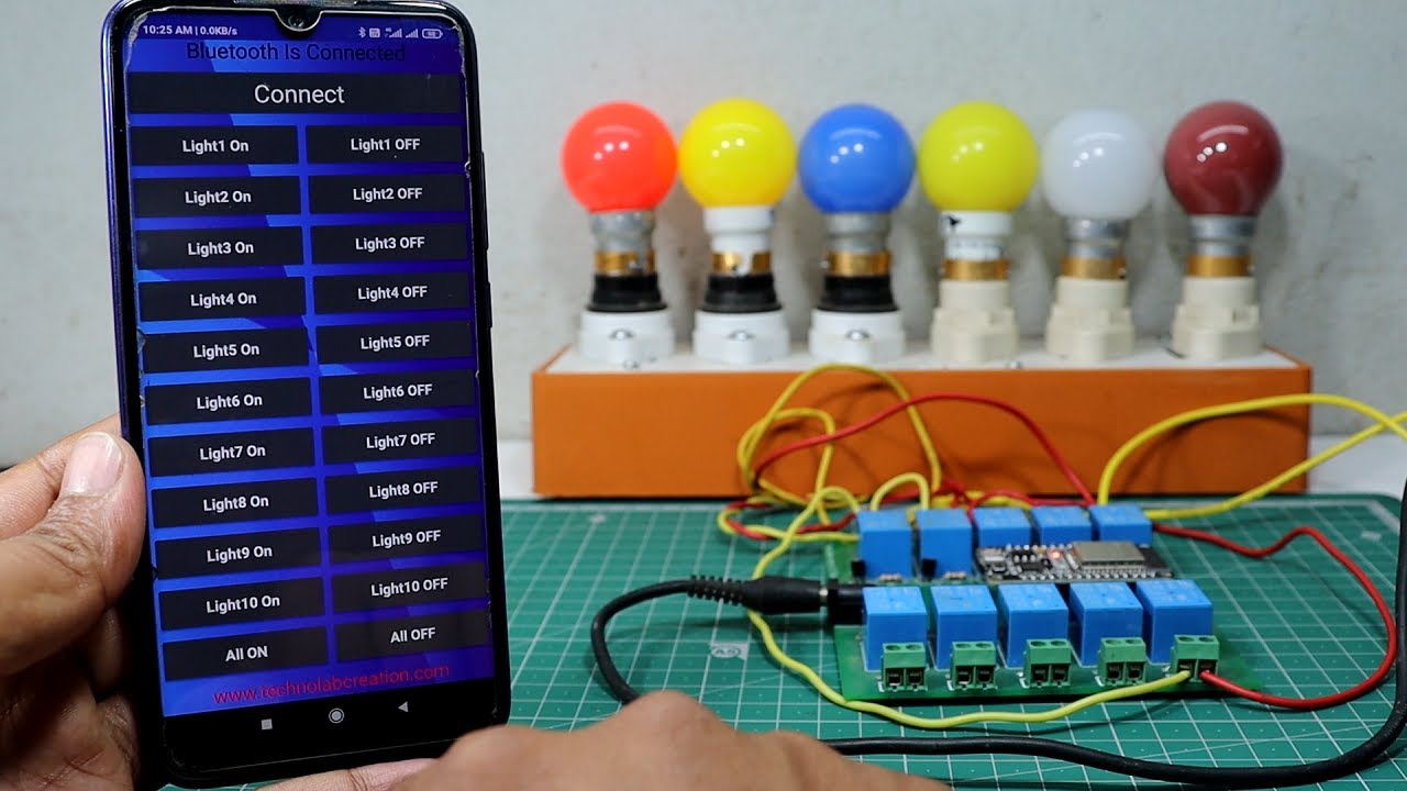
// define the GPIO connected with Relays and switches
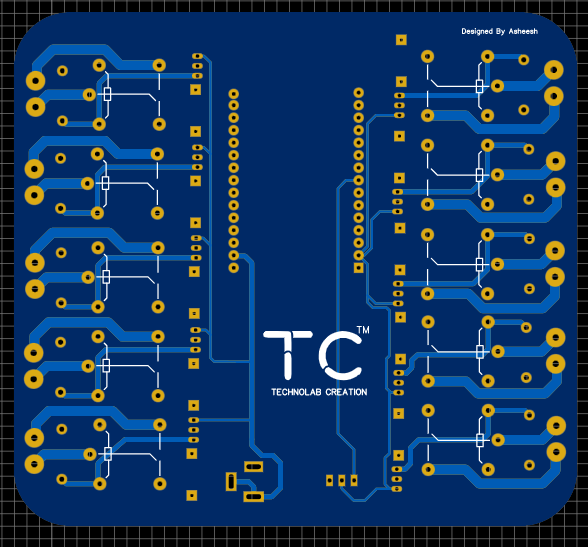
#define RelayPin1 26  
#define RelayPin2 27
#define RelayPin3 14 
#define RelayPin4 12 
#define RelayPin5 13  
#define RelayPin6 21
#define RelayPin7 4 
#define RelayPin8 18
#define RelayPin9 19 
#define RelayPin10 2

char bt_data; // variable for storing bluetooth data 


void all_Switch_ON(){
  digitalWrite(RelayPin1, LOW);  delay(100);
  digitalWrite(RelayPin2, LOW);  delay(100);
  digitalWrite(RelayPin3, LOW);  delay(100);
  digitalWrite(RelayPin4, LOW);  delay(100);
  digitalWrite(RelayPin5, LOW);  delay(100);
  digitalWrite(RelayPin6, LOW);  delay(100);
  digitalWrite(RelayPin7, LOW);  delay(100);
  digitalWrite(RelayPin8, LOW);  delay(100);
  digitalWrite(RelayPin9, LOW);  delay(100);
  digitalWrite(RelayPin10, LOW);  delay(100);

}

void all_Switch_OFF(){
  digitalWrite(RelayPin1, HIGH); delay(100);
  digitalWrite(RelayPin2, HIGH); delay(100);
  digitalWrite(RelayPin3, HIGH); delay(100);
  digitalWrite(RelayPin4, HIGH); delay(100);
  digitalWrite(RelayPin5, HIGH); delay(100);
  digitalWrite(RelayPin6, HIGH); delay(100);
  digitalWrite(RelayPin7, HIGH); delay(100);
  digitalWrite(RelayPin8, HIGH); delay(100);
  digitalWrite(RelayPin9, HIGH); delay(100);
  digitalWrite(RelayPin10, HIGH); delay(100);

}

void Bluetooth_handle()
{
  bt_data = SerialBT.read();
  Serial.println(bt_data);
  delay(20);

  switch(bt_data)
      {
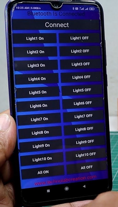
        case 'A': digitalWrite(RelayPin1, LOW);   break; // if 'A' received Turn off Relay1
        case 'a': digitalWrite(RelayPin1, HIGH);  break; // if 'a' received Turn on Relay1
        case 'B': digitalWrite(RelayPin2, LOW);   break; // if 'B' received Turn off Relay2
        case 'b': digitalWrite(RelayPin2, HIGH);  break; // if 'b' received Turn on Relay2
        case 'C': digitalWrite(RelayPin3, LOW);   break; // if 'C' received Turn off Relay3
        case 'c': digitalWrite(RelayPin3, HIGH);  break; // if 'c' received Turn on Relay3
        case 'D': digitalWrite(RelayPin4, LOW);   break; // if 'D' received Turn off Relay4
        case 'd': digitalWrite(RelayPin4, HIGH);  break; // if 'd' received Turn on Relay4
        case 'E': digitalWrite(RelayPin5, LOW);   break; // if 'E' received Turn off Relay5
        case 'e': digitalWrite(RelayPin5, HIGH);  break; // if 'e' received Turn on Relay5
        case 'F': digitalWrite(RelayPin6, LOW);   break; // if 'F' received Turn off Relay6
        case 'f': digitalWrite(RelayPin6, HIGH);  break; // if 'f' received Turn on Relay6
        case 'G': digitalWrite(RelayPin7, LOW);   break; // if 'G' received Turn off Relay7
        case 'g': digitalWrite(RelayPin7, HIGH);  break; // if 'g' received Turn on Relay7
        case 'H': digitalWrite(RelayPin8, LOW);   break; // if 'H' received Turn off Relay8
        case 'h': digitalWrite(RelayPin8, HIGH);  break; // if 'h' received Turn on Rela8
        case 'I': digitalWrite(RelayPin9, LOW);   break; // if 'I' received Turn off Relay9
        case 'i': digitalWrite(RelayPin9, HIGH);  break; // if 'i' received Turn on Relay9
        case 'J': digitalWrite(RelayPin10, LOW);   break; // if 'J' received Turn off Relay10
        case 'j': digitalWrite(RelayPin10, HIGH);  break; // if 'j' received Turn on Relay10
        case 'K': all_Switch_ON(); break;  // if 'K' received Turn on all Relays
        case 'k': all_Switch_OFF(); break; // if 'k' received Turn off all Relays
        default : break;
      }
}

void setup()
{
  Serial.begin(9600);

  btStart();  //Serial.println("Bluetooth On");
  
  SerialBT.begin("HA_BT_ESP32"); //Bluetooth device name
  Serial.println("The device started, now you can pair it with bluetooth!");
  delay(5000);

  pinMode(RelayPin1, OUTPUT);
  pinMode(RelayPin2, OUTPUT);
  pinMode(RelayPin3, OUTPUT);
  pinMode(RelayPin4, OUTPUT);
  pinMode(RelayPin5, OUTPUT);
  pinMode(RelayPin6, OUTPUT);
  pinMode(RelayPin7, OUTPUT);
  pinMode(RelayPin8, OUTPUT);
  pinMode(RelayPin9, OUTPUT);
  pinMode(RelayPin10, OUTPUT);


  //During Starting all Relays should TURN OFF
  digitalWrite(RelayPin1, LOW);
  digitalWrite(RelayPin2, LOW);
  digitalWrite(RelayPin3, LOW);
  digitalWrite(RelayPin4, LOW);
  digitalWrite(RelayPin5, LOW);
  digitalWrite(RelayPin6, LOW);
  digitalWrite(RelayPin7, LOW);
  digitalWrite(RelayPin8, LOW);
  digitalWrite(RelayPin9, LOW);
  digitalWrite(RelayPin10, LOW);
   
   delay(200);
}

void loop()
{  
  if (SerialBT.available()){
   Bluetooth_handle();
 }

}


One thing you could change if you want, the name of Bluetooth device and rest of thing is OK .

Uplaod the code in your Arduino Board ,After selecting right board and COM Port.

SerialBT.begin("HA_BT_ESP32"); //Bluetooth device name

Thanks for the reading!!

2 thoughts on “ESP32 Bluetooth Controlled 10Ch HomeAutomation System Using Android App.

Leave a Reply

Your email address will not be published. Required fields are marked *

Back To Top