On a recent visit to my village, I noticed that many farmers have motor pumps installed far from their homes, directly in the farming areas. Operating these pumps can be challenging, as it requires frequent trips to the fields just to turn them on or off. This sparked an idea for a solution.
I’ve developed an automation system that allows anyone to control their motor pump via a missed call. Yes, you heard right! To operate the pump, simply send a missed call to a preset number, and the system will toggle the pump’s status. Additionally, you’ll receive a feedback SMS on your phone indicating whether the motor is on or off.This simple yet effective project is designed to ease the lives of farmers and can be adapted for any remote device management.
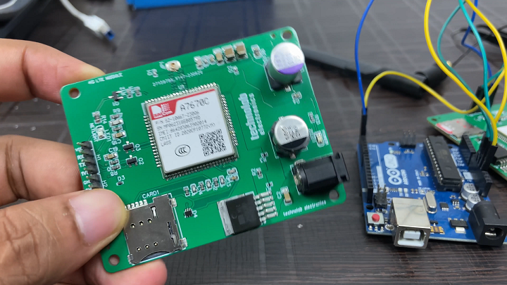
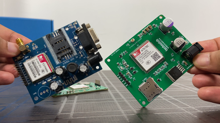
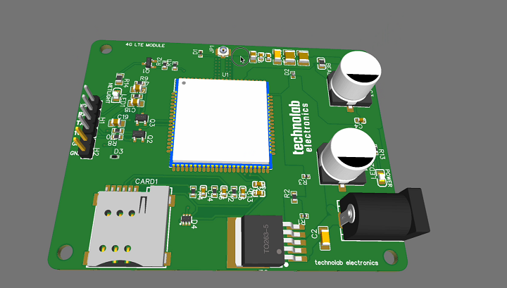
The backbone of this project is a 4G LTE module, supported by JLCPCB SMT Assembly Services.For those interested in the technical details, I’ve covered the features and specifications of this 4G LTE module in a dedicated Article. This includes its advantages over traditional 2G GSM modules and guidance on connecting it with an Arduino Uno board.Click here to read the full Article.
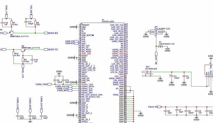
PCB Design.
After making the Schematic, Convert it into PCB, Arrange and place all the components in desirable places, Once the layout is ready route the wiring and complete the design of PCB.
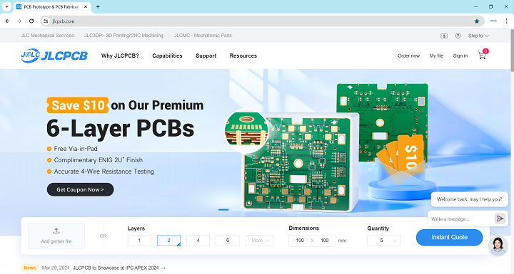
JLCPCB.
In this project, a crucial component is the precision and reliability provided by the 4G LTE Module, a product that came to fruition with the expertise of JLCPCB. As the leading PCB (Printed Circuit Board) manufacturing company, JLCPCB offers state-of-the-art SMT (Surface Mount Technology) assembly services that enable hobbyists and professionals alike to bring their electronic projects to life with ease and affordability.
Whether you’re building a simple DIY project or developing complex industrial applications, JLCPCB has the capabilities to meet your needs. They provide a fast turnaround on orders, often shipping within 24 hours, and their pricing is transparent and highly competitive, making high-quality PCBs accessible to everyone.
What sets JLCPCB apart is their commitment to quality and customer service. Their website, JLCPCB, offers a user-friendly experience where you can easily upload your PCB design files, view instant quotes, and track the production process in real-time. With JLCPCB’s robust service offerings, you’re not just purchasing a product; you’re investing in a partnership that empowers your innovations.
For those who are curious about integrating JLCPCB’s services into your own projects, I encourage you to explore their website and discover the various services they offer that can enhance your electronic designs. This project wouldn’t have been possible without their exceptional PCB assembly service, proving that JLCPCB is not just a supplier, but a critical partner in the world of electronics.
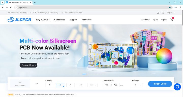
JLCPCB's Multi-Color Silkscreen PCBs.
JLCPCB—their Multi-Color Silkscreen PCB service. This cutting-edge service allows the integration of multiple colors onto the surface of printed circuit boards, transforming standard PCBs from purely functional components into visually striking elements of any hardware project.
Traditional silkscreen PCBs typically feature monochromatic designs, limiting their use to functional labels for component placements and simple logos. JLCPCB has revolutionized this by introducing their Multi-Color Silkscreen service, which supports vibrant and detailed graphics, enhancing both the aesthetics and functionality of your PCBs. Whether it’s intricate logos, detailed graphical instructions, or simply artistic designs, JLCPCB’s service enables a new level of creative expression.
Utilizing premium UV curable inks that are both eco-friendly and resilient against fading and heat, JLCPCB ensures that your designs are not only striking but durable. The process is simple and integrated with JLCPCB’s online platform, where you can upload and manage your designs easily. Their state-of-the-art 6-color UV printer guarantees ultra-high resolution prints, making it possible to achieve exceptional detail on every PCB.
Additionally, JLCPCB offers this service at a starting price of just $4.7, adding only a day to the standard production timeline, which makes it a cost-effective and timely solution for enhancing your electronic projects. To help users get started, JLCPCB has also introduced a limited-time offer that includes a special discount for those who join their official user group.
For more detailed guidance on designing with Multi-Color Silkscreen, JLCPCB provides comprehensive support through EasyEDA tools, making it easy for anyone from hobbyists to professional designers to bring their colorful PCBs to life.
CODE.
Click here to download the Code.
#include <SoftwareSerial.h>

SoftwareSerial gsmSerial(9, 10); // RX, TX for the GSM module
int MotorPin = 13; // Motor connected to digital pin 13

void setup() {
    pinMode(MotorPin, OUTPUT); // Initialize the digital pin as an output
    gsmSerial.begin(9600);   // Set baud rate for the GSM module
    Serial.begin(9600);      // Set baud rate for serial communication with PC

    Serial.println("Ready...");
    delay(1000);

    // Turn off echo
    gsmSerial.println("ATE0");
    delay(1000);

    // Set SMS text mode
    gsmSerial.println("AT+CMGF=1");
    delay(1000);
}

void loop() {
    if (gsmSerial.available()) {
        String inputString = gsmSerial.readString();
        Serial.print(inputString); // You can see the GSM module output in the Serial Monitor

        // Check if the string contains "RING"
        if (inputString.indexOf("RING") != -1) {
            toggleMOTOR(); // Toggle the Motor state on receiving a call
            // Optionally, you can hang up the call
            gsmSerial.println("ATH"); // Send hang-up command to the GSM module
        }
    }
}

void toggleMOTOR() {
    static bool motorState = false;
    motorState = !motorState;
    digitalWrite(MotorPin, motorState ? HIGH : LOW);

    // Send SMS notification
    String smsMessage = motorState ? "Motor is ON" : "Motor is OFF";
    sendSMS("+918543053029", smsMessage); // Replace with your phone number
}

void sendSMS(String number, String text) {
    gsmSerial.println("AT+CMGS=\"" + number + "\"");
    delay(1000);
    gsmSerial.println(text);
    delay(1000);
    gsmSerial.write(26); // ASCII code for CTRL+Z
}
This code is an Arduino sketch that interfaces with a GSM module to control a motor based on incoming phone calls. It also sends SMS notifications about the motor’s state. Here’s a detailed breakdown of the code:
#include <SoftwareSerial.h>
This line includes the SoftwareSerial library, which allows the use of digital pins on the Arduino to emulate serial communication. This is particularly useful for communicating with the GSM module without using the primary hardware serial port.
SoftwareSerial gsmSerial(9, 10); // RX, TX for the GSM module
This line creates an instance of SoftwareSerial named gsmSerial with digital pins 9 and 10 serving as the receiver (RX) and transmitter (TX) respectively for the GSM module.
int MotorPin = 13; // Motor connected to digital pin 13
This defines an integer variable MotorPin and initializes it to 13, which is the pin connected to the motor.
pinMode(MotorPin, OUTPUT); // Initialize the digital pin as an output
Sets the mode of the MotorPin as an output pin, which is necessary for controlling the motor.
    gsmSerial.begin(9600);   // Set baud rate for the GSM module
    Serial.begin(9600);      // Set baud rate for serial communication with PC
These lines initialize serial communication. gsmSerial.begin(9600) starts serial communication with the GSM module at 9600 baud rate. Serial.begin(9600) starts serial communication with the connected computer at the same baud rate for debugging or monitoring.
    // Turn off echo
    gsmSerial.println("ATE0");
    delay(1000);
Sends the command ATE0 to the GSM module to turn off echo, which stops the module from sending a copy of received commands back to the sender. This is followed by a one-second delay.
    // Set SMS text mode
    gsmSerial.println("AT+CMGF=1");
    delay(1000);
Sends AT+CMGF=1 to the GSM module to configure it to send SMS in text mode. Another one-second delay follows.
if (gsmSerial.available()) {
Checks if there is any data available to read from the GSM module.
String inputString = gsmSerial.readString();
Serial.print(inputString); // You can see the GSM module output in the Serial Monitor
Reads the incoming data as a string from the GSM module and prints it to the Serial Monitor.
// Check if the string contains "RING"
if (inputString.indexOf("RING") != -1) {
Checks if the incoming data contains the substring “RING”, which indicates an incoming call.
toggleMOTOR(); // Toggle the Motor state on receiving a call
// Optionally, you can hang up the call
gsmSerial.println("ATH"); // Send hang-up command to the GSM module
Calls the toggleMOTOR() function to toggle the motor’s state and sends the ATH command to hang up the call.
void toggleMOTOR() {
Defines a function to toggle the state of the motor.
Uses a static boolean variable motorState to keep track of the motor’s state. Toggles this state and sets the MotorPin to HIGH if motorState is true, otherwise sets it to LOW.
// Send SMS notification
String smsMessage = motorState ? "Motor is ON" : "Motor is OFF";
sendSMS("+918543053029", smsMessage); // Replace with your phone number
repares an SMS message indicating whether the motor is ON or OFF and calls sendSMS function to send this message.
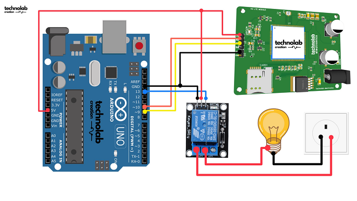
Make all the connection as per the below connection diagram.
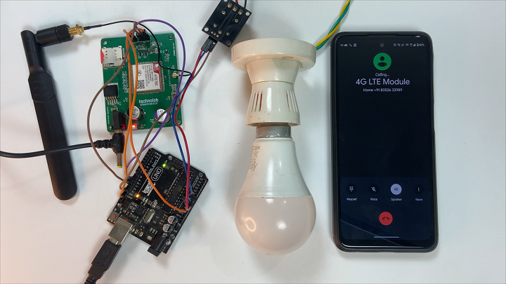
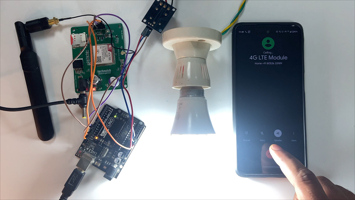
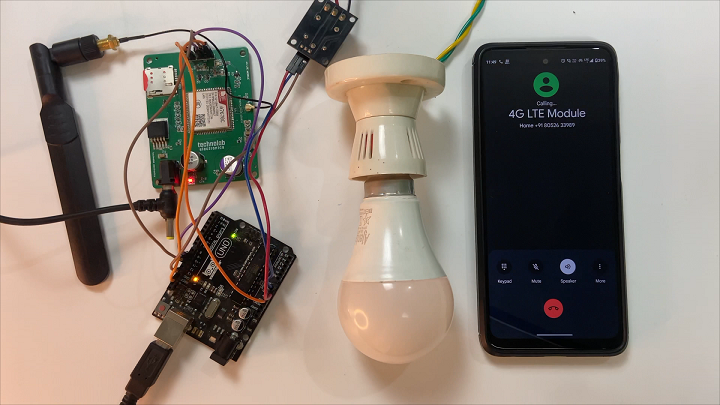
To demonstrate this system in action. I’m using an AC bulb here for the demo.
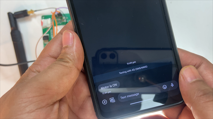
When I make a missed call to the GSM Module, the bulb turns on, and I immediately receive a text message stating, “Motor is ON.”
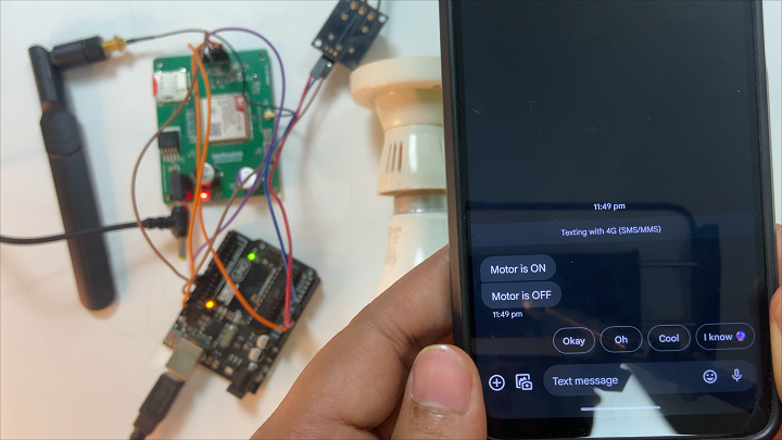
Let me turn off the bulb with another missed call—there, it’s off, and a confirmation SMS follows, “Motor is OFF.”
This automation system is not only useful for farmers but can be a significant convenience for anyone needing to manage remote devices via missed calls.
That’s it for this Article. I hope you found it informative.