In the era of IoT and smart devices, integrating cellular technology like 4G LTE with microcontrollers such as the Arduino Uno opens up a myriad of possibilities. From sending SMS messages and making calls to transmitting data over the internet, the combination of Arduino and 4G LTE modules paves the way for advanced projects. In this article, we’ll explore how to use a 4G LTE module with an Arduino Uno to send text messages, receive SMS, and make phone calls.
Introduction to 4G LTE and Arduino Uno.
4G LTE stands for “fourth-generation long-term evolution” and offers high-speed internet and communication capabilities. When combined with the versatility of the Arduino Uno, a popular microcontroller board based on the ATmega328P, it allows hobbyists and professionals to create projects that communicate over cellular networks.
Project Overview.
Our project involves interfacing a 4G LTE module with an Arduino Uno to perform three primary tasks:
Sending SMS messages.
Receiving live SMS.
Making phone calls.
We will use the SoftwareSerial library in Arduino to create a serial connection between the Arduino Uno and the 4G LTE module.
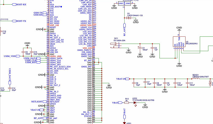
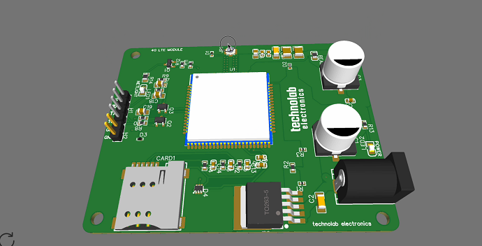
PCB Design.
This is the Schematic of 4G LTE Module.
After making the Schematic, Convert it into PCB, Arrange and place all the components in desirable places, Once the layout is ready route the wiring and complete the design of PCB.
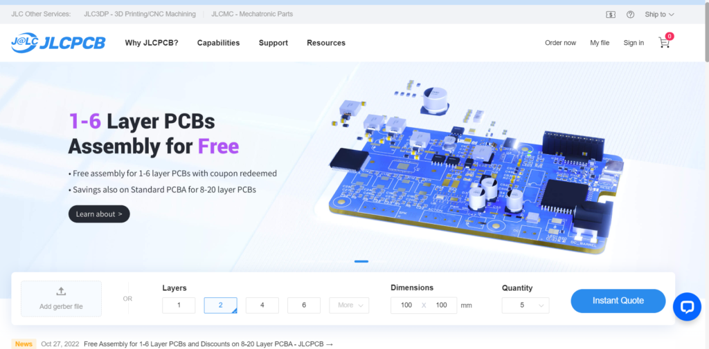
JLCPCB
This article is sponsored by JLCPCB , a leading manufacturer specializing in PCB prototype and fabrication. With their fully automated production lines housed in their own factories, they guarantee excellent quality and consistency in their products, adhering to certifications such as ISO 9001:2015, ISO 14001:2015, and IPC-6012E.
JLCPCB is not only renowned for its high-quality PCBs but also for its extraordinary savings and guaranteed satisfaction. They offer a range of services including PCB assembly with over 350,000 in-stock parts, 3D printing with various materials like resin, nylon, and metal, and high-precision SMT stencils created with state-of-the-art LPKF machines.
Experience fast and stable delivery with JLCPCB, where over 98% of orders are shipped on time, allowing you to iterate your projects more freely with their low-cost and fast-turnaround services. Moreover, their friendly support team is available 24 hours a day through email, live chat, and phone to assist you at any time.
Choose JLCPCB as your PCB partner to enjoy quality products, extraordinary savings, and guaranteed satisfaction.
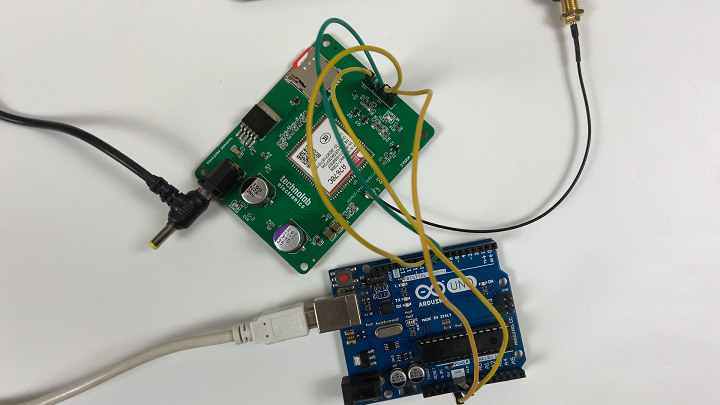
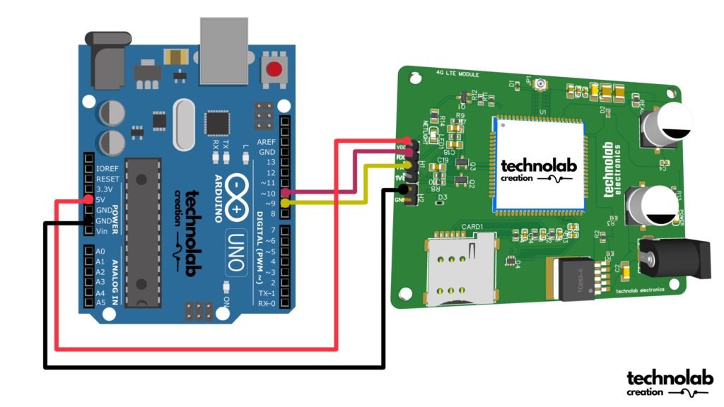
Setting Up the Hardware.
Connect the 4G LTE Module to Arduino Uno: Use digital pins 9 and 10 of the Arduino to connect with the TX and RX pins of the 4G LTE module, respectively.
Take refrence from above Coneection diagram.
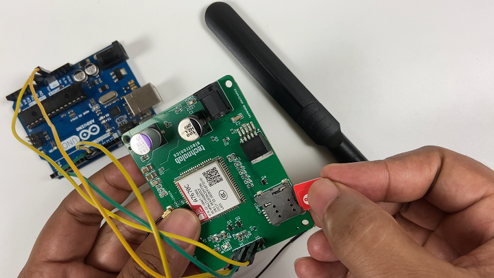
Insert SIM Card:
Place a SIM card into the 4G LTE module and you can use any simcard either 2G or 4G.
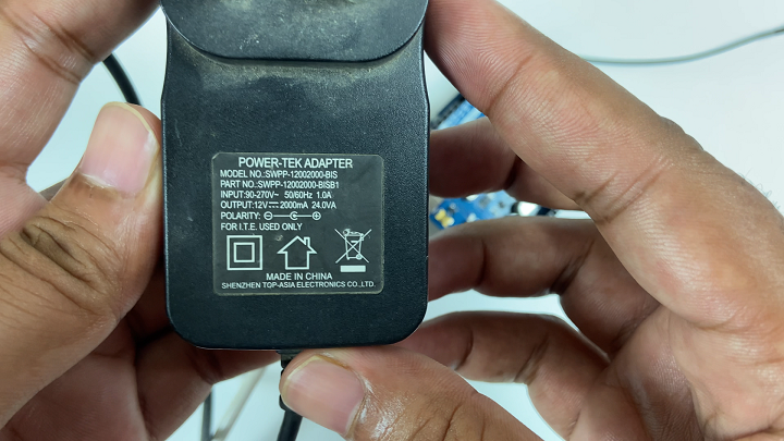
Power Supply:
Use 12Volt and 2 Amp Power Supply, apart from any other power supply it will not work properly.
CODE.
Click here to download the Code.
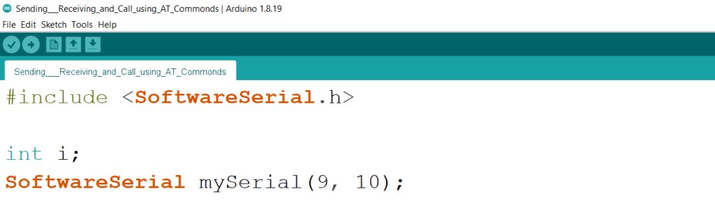
#include <SoftwareSerial.h>
int i;
SoftwareSerial mySerial(9, 10);
void setup()
{
mySerial.begin(9600); // Setting the baud rate of 4G LTE Module
Serial.begin(9600); // Setting the baud rate of Serial Monitor (Arduino)
delay(100);
}
void loop()
{
if (Serial.available()>0)
switch(Serial.read())
{
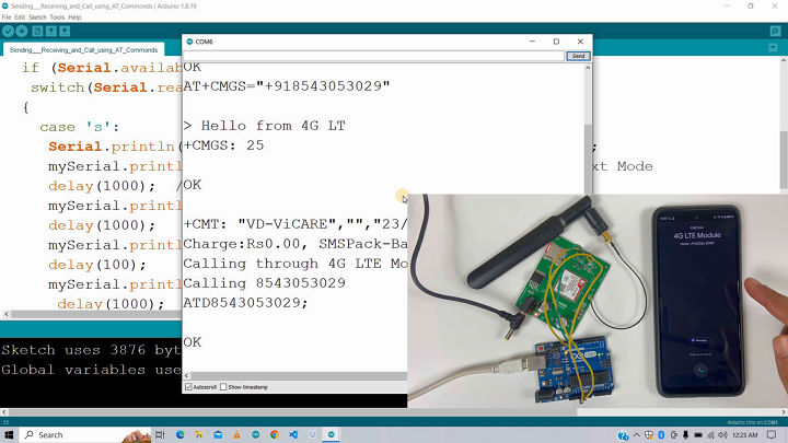
case 's':
Serial.println("Sending text Message through 4G LTE Module");
mySerial.println("AT+CMGF=1"); //Sets the 4G Module in Text Mode
delay(1000); // Delay of 1 second
mySerial.println("AT+CMGS=\"+91XXXXXXXXXX\"\r"); // Replace x with mobile number
delay(1000);
mySerial.println("Hello from 4G LTE Module");// The SMS text you want to send
delay(100);
mySerial.println((char)26);// ASCII code of CTRL+Z for saying the end of sms to the module
delay(1000);
break;
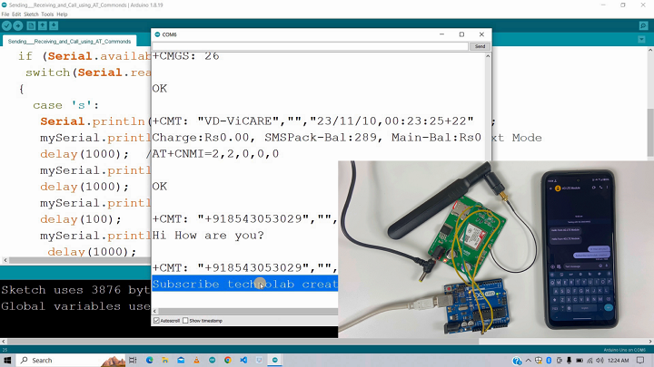
case 'r':
mySerial.println("AT+CNMI=2,2,0,0,0"); // AT Command to receive a live SMS
delay(1000);
break;
case 'c':
if(i==0)//i variable to ensure that only one call request will be sent by gsm during pressing and holding the pushbutton;
{
Serial.println("Calling through 4G LTE Module");
delay(1000);
mySerial.println("ATD8543053029;"); // ATDxxxxxxxxxx; semicolon should be at the last ;AT command that follows UART protocol;
Serial.println("Calling 8543053029");
delay(1000);
i++;
}
i=0;
break;
}
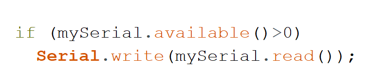
if (mySerial.available()>0)
Serial.write(mySerial.read());
}
The provided code is for an Arduino sketch that interfaces with a GSM module using the SoftwareSerial library. The GSM module is connected to the Arduino through digital pins 9 and 10. The sketch allows the user to send text messages, receive live SMS, and make phone calls through the GSM module by sending appropriate AT commands. Here’s a breakdown of the code:
Include SoftwareSerial Library:
This line includes the SoftwareSerial library, which allows for serial communication on other digital pins of the Arduino, not just the default 0 and 1.
Variable Declaration:
An integer ‘i’ is declared for later use. A ‘SoftwareSerial’ object named ‘mySerial’ is created on digital pins 9 and 10.
setup() Function:
This function is called once when the sketch starts. It initializes the serial communication.
‘mySerial.begin(9600);’: Begins serial communication with the GSM module at 9600 baud.
‘Serial.begin(9600);‘: Begins serial communication with the computer (Serial Monitor) at 9600 baud.
‘delay(100);’: A short delay to ensure everything is initialized properly.
loop() Function:
This function runs repeatedly after ‘setup()’.
It checks if there is any data available on the Serial Monitor.
Depending on the character received (‘s’, ‘r’, or ‘c’), it performs different actions:
‘s’ for Sending SMS:
Sends the command AT+CMGF=1 to set the GSM module to text mode.
Sends the command AT+CMGS=\”+91XXXXXXXXXX\” to set the recipient’s phone number (replace with the desired number).
Sends the actual message text (“Hello from 4G LTE Module”).
Sends ASCII code 26 (Ctrl+Z) to indicate the end of the SMS.
‘r’ for Receiving SMS:
Sends the command AT+CNMI=2,2,0,0,0 to configure the GSM module to receive live SMS.
‘c’ for Making a Call:
Checks if i is 0 to prevent multiple call requests.
Sends the command ATDXXXXXXXXXX; to dial the specified number (replace with the desired number).
Resets i to 0 after the call attempt.
If there is any data available from the GSM module (mySerial), it is printed to the Serial Monitor.
Note: The phone numbers in the code are placeholders and should be replaced with actual numbers when using the sketch. Also, ensure that the GSM module is compatible with the Arduino and is properly powered and connected.
The provided sample code is a basic implementation of these functions. It listens for user input via the Serial Monitor and performs actions based on the input – ‘s’ for sending SMS, ‘r’ for receiving SMS, and ‘c’ for making a call.
Safety and Testing.
Before deploying the project, it’s crucial to test each functionality in a controlled environment. Ensure that the SIM card has no barring services for calls or SMS.
Applications and Advancements.
This setup can be the foundation for numerous applications, including:
Remote monitoring systems.
Automated alert messages in IoT systems.
Emergency communication systems.
For advanced users, integrating IoT platforms, adding GPS functionality, or connecting to cloud services can further enhance the project’s capabilities.
Conclusion
The integration of 4G LTE modules with Arduino Uno offers a powerful tool for creating communication-based projects. Whether it’s for learning, prototyping, or building a product, the potential is vast and limited only by one’s imagination. As technology advances, we can anticipate even more sophisticated and seamless integration in this domain
3 thoughts on “4G LTE Module : How to Send, Receive & Make Call using AT Commands.”
Hi,
They are closing down 2g and 3g system here in sweden. And on my volvo there is thing called Volvo on call that runs on that system. Is it possible to replace that module to an 4g module? And will all options in the app still work after replacement?
Best regards
Magnus Ledin
When I am using this 4g lte with esp32,I am connecting with 5v 5amp adaptor,So if got error and not able to connect with server using http and not able to make calls,sms, receive calls.What can I do?


Hi,
They are closing down 2g and 3g system here in sweden. And on my volvo there is thing called Volvo on call that runs on that system. Is it possible to replace that module to an 4g module? And will all options in the app still work after replacement?
Best regards
Magnus Ledin
We need to check the internal circuit.
Hi
When I am using this 4g lte with esp32,I am connecting with 5v 5amp adaptor,So if got error and not able to connect with server using http and not able to make calls,sms, receive calls.What can I do?