

Introduction.
In the realm of home automation, the evolution of technology offers endless possibilities. The recent launch of the Arduino Nano ESP32 board is a game-changer, breathing new life into older systems. In this article, we’ll explore how an old home-automation PCB, originally designed for the Arduino Nano, can be rejuvenated using the Arduino Nano ESP32. This integration not only adds Wi-Fi and Bluetooth capabilities but also opens up a plethora of IoT opportunities.
Background: The Legacy System
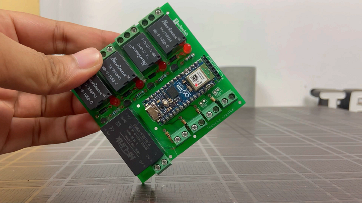
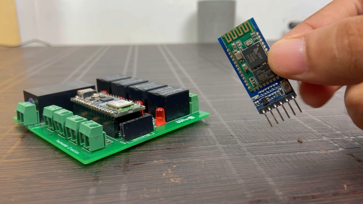
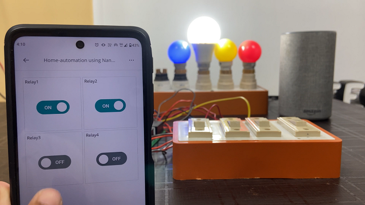
Our journey begins with a legacy home-automation system – a project that allowed control of four household appliances using a smartphone app and manual switch buttons. This system, built around an old home-automation PCB designed for the Arduino Nano, served well but lacked IoT capabilities due to the absence of built-in Wi-Fi and Bluetooth in the Arduino Nano.

Arduino Nano ESP32
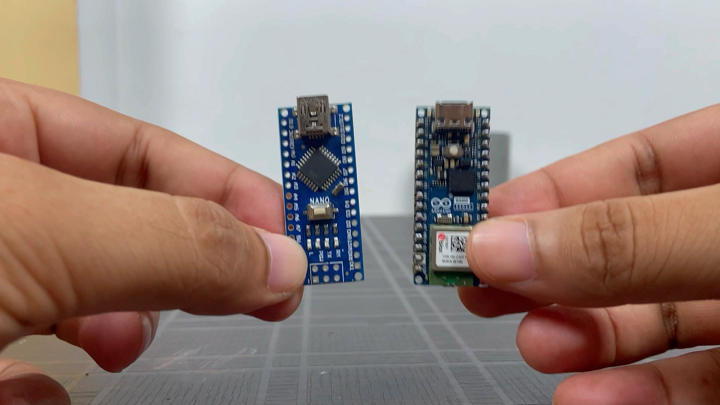
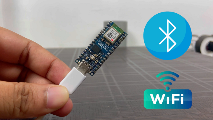
The Arduino Nano ESP32 board, mirroring the form factor of its predecessor, is a powerhouse with built-in Wi-Fi and Bluetooth. This advancement means that the same PCB can now be used for IoT projects, transforming the old system into a smart, connected, and more versatile home automation solution.

Features & Specifications of Arduino Nano ESP32.
The Arduino Nano ESP32 is a versatile and powerful board ideal for IoT development, offering a range of features and specifications:
1.Microcontroller: It features the u-blox® NORA-W106 module with an ESP32-S3 chip, providing robust processing capabilities.
2.Connectivity: The board supports both Wi-Fi and Bluetooth (5.0 and above), enabling a wide range of IoT applications.
3.USB-C® Connector: This is the first Nano board to include a USB-C connector, enhancing its connectivity options.
4.Debugging: It supports out-of-the-box debugging without additional hardware.
5.ESP-NOW Protocol: The board supports the ESP-NOW protocol developed by Espressif.
6.Technical Specifications:
Operating Voltage: The microcontroller operates at 3.3V.
- Digital I/O Pins: 14
- Analog Input Pins: 8
- PWM Pins: All pins (maximum of 5 simultaneously)
- External Interrupts: Available on all digital pins
- I/O Pin Voltage: 3.3V
- Input Voltage (Nominal): 6-21V
- Source Current per I/O Pin: 40mA
- Sink Current per I/O Pin: 28mA
- Clock Speed: Processor up to 240 MHz
- Memory: 384 kB ROM, 512 kB SRAM, and 128 Mbit (16 MB) External Flash.
7.Compatibility with Arduino IoT Cloud: This board is fully compatible with the Arduino IoT Cloud platform, allowing for easy creation and management of IoT projects.
These features make the Arduino Nano ESP32 a powerful and flexible tool for a wide range of applications, from simple DIY projects to complex IoT solutions.
JLCPCB.
- This article is sponsored by JLCPCB , a leading manufacturer specializing in PCB prototype and fabrication. With their fully automated production lines housed in their own factories, they guarantee excellent quality and consistency in their products, adhering to certifications such as ISO 9001:2015, ISO 14001:2015, and IPC-6012E.
- JLCPCB is not only renowned for its high-quality PCBs but also for its extraordinary savings and guaranteed satisfaction. They offer a range of services including PCB assembly with over 350,000 in-stock parts, 3D printing with various materials like resin, nylon, and metal, and high-precision SMT stencils created with state-of-the-art LPKF machines.
- Experience fast and stable delivery with JLCPCB, where over 98% of orders are shipped on time, allowing you to iterate your projects more freely with their low-cost and fast-turnaround services. Moreover, their friendly support team is available 24 hours a day through email, live chat, and phone to assist you at any time.
- Choose JLCPCB as your PCB partner to enjoy quality products, extraordinary savings, and guaranteed.
Arduino IOT Cloud Configuration.
Configuring the Arduino IoT Cloud for a home automation system that controls four devices involves several key steps. Here’s a step-by-step guide to get you started:
Step 1: Create an Arduino Account
- Sign Up: If you don’t already have an Arduino account, visit [Arduino’s website] and sign up.
- Log In: Log into your account to access the Arduino IoT Cloud.
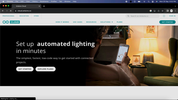
Step 2: Access Arduino IoT Cloud
- Navigate: Once logged in, find the Arduino IoT Cloud in the services section or visit [Arduino IoT Cloud]directly.
Step 3: Set Up a New Thing
- Create a New Thing: In the Arduino IoT Cloud dashboard, select “Create Thing”.
- Name Your Thing: Give your “Thing” a descriptive name, like “HomeAutomationSystem”.
Step 4: Add Properties
- Define Properties: For each device (e.g., light, fan), add a property.
- Configure Properties:
- Name: Assign a name to each property like “LivingRoomLight”.
- Type: Select an appropriate type, such as ‘Boolean’ for ON/OFF states.
- Permission: Choose “Read and Write” to allow controlling the device through the Cloud.
- Update Policy: Select “On Change” for real-time updates.
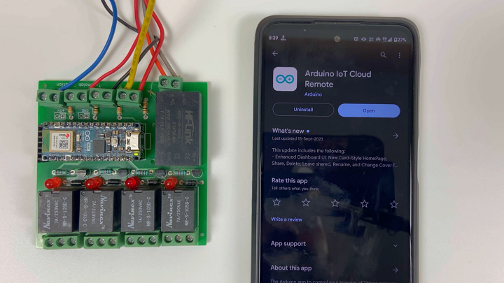
Step 5: Linking Your Device
- Choose Your Device: Click on “Devices” tab and select “Set up a Device”.
- Select the Board: Choose the Arduino Nano ESP32 from the list of boards.
- Connect the Board: Follow the instructions to connect your board to the Arduino IoT Cloud. This typically involves connecting it to your computer via USB and selecting the correct port.
Step 6: Network Configuration
- Wi-Fi Setup: Input your Wi-Fi credentials to allow your Arduino Nano ESP32 to connect to the internet.
Step 7: Assign Properties to the Device
- Link Properties: Go back to your Thing and link each property to the corresponding device.
Step 8: Writing the Sketch
- Auto-Generate Sketch: Arduino IoT Cloud can auto-generate a base sketch.
- Modify the Sketch: Customize the sketch to control your devices. Add code to control the GPIO pins connected to your relays or other control circuits.
Step 9: Upload the Sketch
- Upload: Use the Arduino IDE to upload the sketch to your Arduino Nano ESP32.
Step 10: Test and Debug
- Test: Test each device control through the Arduino IoT Cloud Dashboard.
- Debug: Troubleshoot any issues, such as connectivity or control problems.
Step 11: Creating Dashboard Widgets
- Add Widgets: In the dashboard, add widgets for each property.
- Configure Widgets: Customize widgets (like buttons or sliders) to control your devices.
Step 12: Final Testing
- Operate Devices: Use the widgets on the dashboard to control and monitor your devices.
- Check Manual Override: Ensure manual switch buttons work in tandem with IoT control.
Once everything is set up and tested, your home automation system is ready to use. You can now control and monitor your four devices through the Arduino IoT Cloud, providing a seamless and smart home automation experience. Remember, the key to a successful IoT project is thorough testing and iterative improvements based on real-world usage.
Code.
#include "arduino_secrets.h"
/*
  Sketch generated by the Arduino IoT Cloud Thing "Untitled"
  https://create.arduino.cc/cloud/things/1ff00950-7b48-4205-ad1c-da3936fb10b2

  Arduino IoT Cloud Variables description

  The following variables are automatically generated and updated when changes are made to the Thing

  CloudDimmedLight fan;
  CloudLight relay1;
  CloudLight relay2;
  CloudLight relay3;
  CloudLight relay4;
  CloudTemperatureSensor temperature;
  CloudRelativeHumidity humidity;


  Variables which are marked as READ/WRITE in the Cloud Thing will also have functions
  which are called when their values are changed from the Dashboard.
  These functions are generated with the Thing and added at the end of this sketch.
*/


#include "thingProperties.h"
#include "DHT.h"
#include <IRremote.h>   // https://github.com/Arduino-IRremote/Arduino-IRremote (3.6.1)
#include <AceButton.h>  // https://github.com/bxparks/AceButton (1.9.2)

#define DHTPIN D9
#define DHTTYPE DHT11
#define irPin D11  // IR sensor pin

DHT dht(DHTPIN, DHTTYPE);

using namespace ace_button;

bool DEBUG_SW = 1;

// Pins of Fan Regulator Knob
#define fan_switch A4
#define s1 A3
#define s2 A2
#define s3 A1
#define s4 A0

// Pins of Switches
#define S5 A5
#define S6 A6
#define S7 A7
#define S8 D13

// Pins of Relay (Appliances Control)
#define R5 D2
#define R6 D3
#define R7 D4
#define R8 D5

// Pins of Relay (Fan Speed Control)
#define Speed1 D6
#define Speed2 D7
#define Speed4 D8

bool speed1_flag = 1;
bool speed2_flag = 1;
bool speed3_flag = 1;
bool speed4_flag = 1;
bool speed0_flag = 1;

int switch_ON_Flag1_previous_I = 0;
int switch_ON_Flag2_previous_I = 0;
int switch_ON_Flag3_previous_I = 0;
int switch_ON_Flag4_previous_I = 0;

int curr_speed = 0;
bool fan_power = 0;

// IR Remote Code for Lights
#define IR_Relay1 0x1FE50AF
#define IR_Relay2 0x1FED827
#define IR_Relay3 0x1FEF807
#define IR_Relay4 0x1FE30CF
#define IR_Relay_All_Off 0x1FE48B7
#define IR_Relay_All_On 0x1FE7887

// IR Remote Code for Fan
#define IR_Speed_Up 0x1FE609F
#define IR_Speed_Dw 0x1FEA05F
#define IR_Fan_off 0x1FE10EF
#define IR_Fan_on 0x1FE906F

IRrecv irrecv(irPin);
decode_results results;

ButtonConfig config1;
AceButton button1(&config1);
ButtonConfig config2;
AceButton button2(&config2);
ButtonConfig config3;
AceButton button3(&config3);
ButtonConfig config4;
AceButton button4(&config4);
ButtonConfig config5;
AceButton button5(&config5);

void handleEvent1(AceButton*, uint8_t, uint8_t);
void handleEvent2(AceButton*, uint8_t, uint8_t);
void handleEvent3(AceButton*, uint8_t, uint8_t);
void handleEvent4(AceButton*, uint8_t, uint8_t);
void handleEvent5(AceButton*, uint8_t, uint8_t);

void setup() {
  // Initialize serial and wait for port to open:
  Serial.begin(115200);

  dht.begin();
  irrecv.enableIRIn();  // Enabling IR sensor

  pinMode(s1, INPUT);
  pinMode(s2, INPUT);
  pinMode(s3, INPUT_PULLUP);
  pinMode(s4, INPUT);
  pinMode(S5, INPUT);
  pinMode(S6, INPUT);
  pinMode(S7, INPUT);
  pinMode(S8, INPUT);

  pinMode(R5, OUTPUT);
  pinMode(R6, OUTPUT);
  pinMode(R7, OUTPUT);
  pinMode(R8, OUTPUT);
  pinMode(Speed1, OUTPUT);
  pinMode(Speed2, OUTPUT);
  pinMode(Speed4, OUTPUT);

  config1.setEventHandler(button1Handler);
  config2.setEventHandler(button2Handler);
  config3.setEventHandler(button3Handler);
  config4.setEventHandler(button4Handler);
  config5.setEventHandler(button5Handler);

  button1.init(S5);
  button2.init(S6);
  button3.init(S7);
  button4.init(S8);
  button5.init(fan_switch);

  // This delay gives the chance to wait for a Serial Monitor without blocking if none is found
  delay(1500);


  // Defined in thingProperties.h
  initProperties();

  // Connect to Arduino IoT Cloud
  ArduinoCloud.begin(ArduinoIoTPreferredConnection);

  /*
     The following function allows you to obtain more information
     related to the state of network and IoT Cloud connection and errors
     the higher number the more granular information you’ll get.
     The default is 0 (only errors).
     Maximum is 4
  */
  setDebugMessageLevel(2);
  ArduinoCloud.printDebugInfo();
}

void loop() {

  ArduinoCloud.update();
  // Your code here
  DHT_SENSOR_READ();
  ir_remote();
  Fan();

  button1.check();
  button2.check();
  button3.check();
  button4.check();
  button5.check();
}

void button1Handler(AceButton* button, uint8_t eventType, uint8_t buttonState)
{
  if (DEBUG_SW) Serial.println("EVENT1");
  switch (eventType) {
    case AceButton::kEventPressed:
      if (DEBUG_SW) Serial.println("kEventPressed");
      relay1 = 1;
      digitalWrite(R5, HIGH);
      break;
    case AceButton::kEventReleased:
      if (DEBUG_SW) Serial.println("kEventReleased");
      relay1 = 0;
      digitalWrite(R5, LOW);
      break;
  }
}

void button2Handler(AceButton* button, uint8_t eventType, uint8_t buttonState)
{
  if (DEBUG_SW) Serial.println("EVENT2");
  //EspalexaDevice* d2 = espalexa.getDevice(1);
  switch (eventType) {
    case AceButton::kEventPressed:
      if (DEBUG_SW) Serial.println("kEventPressed");
      relay2 = 1;
      digitalWrite(R6, HIGH);
      break;
    case AceButton::kEventReleased:
      if (DEBUG_SW) Serial.println("kEventReleased");
      relay2 = 0;
      digitalWrite(R6, LOW);
      break;
  }
}
void button3Handler(AceButton* button, uint8_t eventType, uint8_t buttonState) {
  if (DEBUG_SW) Serial.println("EVENT3");
  //EspalexaDevice* d3 = espalexa.getDevice(2);
  switch (eventType) {
    case AceButton::kEventPressed:
      if (DEBUG_SW) Serial.println("kEventPressed");
      relay3 = 1;
      digitalWrite(R7, HIGH);
      break;
    case AceButton::kEventReleased:
      if (DEBUG_SW) Serial.println("kEventReleased");
      relay3 = 0;
      digitalWrite(R7, LOW);
      break;
  }
}
void button4Handler(AceButton* button, uint8_t eventType, uint8_t buttonState) {
  if (DEBUG_SW) Serial.println("EVENT4");
  //EspalexaDevice* d4 = espalexa.getDevice(3);
  switch (eventType) {
    case AceButton::kEventPressed:
      if (DEBUG_SW) Serial.println("kEventPressed");
      relay4 = 1;
      digitalWrite(R8, HIGH);
      break;
    case AceButton::kEventReleased:
      if (DEBUG_SW) Serial.println("kEventReleased");
      relay4 = 0;
      digitalWrite(R8, LOW);
      break;
  }
}

void button5Handler(AceButton* button, uint8_t eventType, uint8_t buttonState)
{
  if (DEBUG_SW) Serial.println("EVENT5");
  switch (eventType) {
    case AceButton::kEventPressed:
      if (DEBUG_SW) Serial.println("kEventPressed");
      if (curr_speed == 0) {
        speed0();
      }
      if (curr_speed == 1) {
        speed1();
      }
      if (curr_speed == 2) {
        speed2();
      }
      if (curr_speed == 3) {
        speed3();
      }
      if (curr_speed == 4) {
        speed4();
      }
      break;
    case AceButton::kEventReleased:
      if (DEBUG_SW) Serial.println("kEventReleased");
      digitalWrite(Speed1, LOW);
      digitalWrite(Speed2, LOW);
      digitalWrite(Speed4, LOW);
      fan.setSwitch(0);
      fan_power = 0;
      delay(100);
      break;
  }
}

void onRelay1Change() {
  digitalWrite(R5, relay1);
  // Do something
}


void onRelay2Change() {
  digitalWrite(R6, relay2);
  // Do something
}


void onRelay3Change() {
  digitalWrite(R7, relay3);
  // Do something
}


void onRelay4Change() {
  digitalWrite(R8, relay4);
  // Do something
}


void onFanChange()
{
  int fan_speed_map = map(fan.getBrightness(), 0, 100, 0, 4);
  if (fan.getSwitch() == 0)
  {
    speed0();
  }

  if (fan.getSwitch() == 1)
  {
    if (fan_speed_map == 0)
      speed0();
    if (fan_speed_map == 1)
      speed1();
    if (fan_speed_map == 2)
      speed2();
    if (fan_speed_map == 3)
      speed3();
    if (fan_speed_map == 4)
      speed4();
  }  // Do something
}


void Fan()
{
  if (digitalRead(fan_switch) == LOW)
  {
    if (digitalRead(s1) == LOW && speed1_flag == 1) {
      speed1();
      speed1_flag = 0;
      speed2_flag = 1;
      speed3_flag = 1;
      speed4_flag = 1;
      speed0_flag = 1;
    }
    if (digitalRead(s2) == LOW && digitalRead(s3) == HIGH && speed2_flag == 1) {
      speed2();
      speed1_flag = 1;
      speed2_flag = 0;
      speed3_flag = 1;
      speed4_flag = 1;
      speed0_flag = 1;
    }
    if (digitalRead(s2) == LOW && digitalRead(s3) == LOW && speed3_flag == 1) {
      speed3();
      speed1_flag = 1;
      speed2_flag = 1;
      speed3_flag = 0;
      speed4_flag = 1;
      speed0_flag = 1;
    }
    if (digitalRead(s4) == LOW && speed4_flag == 1) {
      speed4();
      speed1_flag = 1;
      speed2_flag = 1;
      speed3_flag = 1;
      speed4_flag = 0;
      speed0_flag = 1;
    }
    if (digitalRead(s1) == HIGH && digitalRead(s2) == HIGH && digitalRead(s3) == HIGH && digitalRead(s4) == HIGH && speed0_flag == 1) {
      speed0();
      speed1_flag = 1;
      speed2_flag = 1;
      speed3_flag = 1;
      speed4_flag = 1;
      speed0_flag = 0;
    }
  }
}


//functions for defining of speeds

// Fan Speed Control

void speed0() {
  //All Relays Off - Fan at speed 0
  Serial.println("SPEED 0");
  digitalWrite(Speed1, LOW);
  digitalWrite(Speed2, LOW);
  digitalWrite(Speed4, LOW);
  fan.setSwitch(0);
  fan.setBrightness(0);
  delay(1000);
}

void speed1() {
  //Speed1 Relay On - Fan at speed 1
  Serial.println("SPEED 1");
  digitalWrite(Speed1, LOW);
  digitalWrite(Speed2, LOW);
  digitalWrite(Speed4, LOW);
  fan.setSwitch(1);
  fan.setBrightness(25);
  curr_speed = 1;
  delay(1000);
  digitalWrite(Speed1, HIGH);
}

void speed2() {
  //Speed2 Relay On - Fan at speed 2
  Serial.println("SPEED 2");
  digitalWrite(Speed1, LOW);
  digitalWrite(Speed2, LOW);
  digitalWrite(Speed4, LOW);
  fan.setSwitch(1);
  fan.setBrightness(50);
  curr_speed = 2;
  delay(1000);
  digitalWrite(Speed2, HIGH);
}

void speed3() {
  //Speed1 & Speed2 Relays On - Fan at speed 3
  Serial.println("SPEED 3");
  digitalWrite(Speed1, LOW);
  digitalWrite(Speed2, LOW);
  digitalWrite(Speed4, LOW);
  fan.setSwitch(1);
  fan.setBrightness(75);
  curr_speed = 3;
  delay(1000);
  digitalWrite(Speed1, HIGH);
  digitalWrite(Speed2, HIGH);
}

void speed4()
{
  //Speed4 Relay On - Fan at speed 4
  Serial.println("SPEED 4");
  digitalWrite(Speed1, LOW);
  digitalWrite(Speed2, LOW);
  digitalWrite(Speed4, LOW);
  fan.setSwitch(1);
  fan.setBrightness(100);
  curr_speed = 4;
  delay(1000);
  digitalWrite(Speed4, HIGH);
}

void DHT_SENSOR_READ() {
  float h = dht.readHumidity();
  float t = dht.readTemperature();

  humidity = h;
  temperature = t;

  Serial.print("temp = ");
  Serial.println(t);
  Serial.print("Humi = ");
  Serial.println(h);
  //delay(100);
}

void ir_remote()
{
  if (DEBUG_SW) Serial.println("Inside IR REMOTE");
  if (irrecv.decode(&results)) {
    if (DEBUG_SW) Serial.println(results.value, HEX);  //print the HEX code
    switch (results.value) {
      case IR_Relay1:
        switch_ON_Flag1_previous_I = !switch_ON_Flag1_previous_I;
        digitalWrite(R5, switch_ON_Flag1_previous_I);
        if (DEBUG_SW) Serial.println("RELAY1 ON");
        relay1 = switch_ON_Flag1_previous_I;
        delay(100);
        break;
      case IR_Relay2:
        switch_ON_Flag2_previous_I = !switch_ON_Flag2_previous_I;
        digitalWrite(R6, switch_ON_Flag2_previous_I);
        relay2 = switch_ON_Flag2_previous_I;
        delay(100);
        break;
      case IR_Relay3:
        switch_ON_Flag3_previous_I = !switch_ON_Flag3_previous_I;
        digitalWrite(R7, switch_ON_Flag3_previous_I);
        relay3 = switch_ON_Flag3_previous_I;
        delay(100);
        break;
      case IR_Relay4:
        switch_ON_Flag4_previous_I = !switch_ON_Flag4_previous_I;
        digitalWrite(R8, switch_ON_Flag4_previous_I);
        relay4 = switch_ON_Flag4_previous_I;
        delay(100);
        break;
      case IR_Relay_All_Off:
        All_Lights_Off();

        break;
      case IR_Relay_All_On:
        All_Lights_On();

        break;
      case IR_Fan_on:
        fan.setSwitch(1);
        if (curr_speed == 0) {
          speed0();
        } else if (curr_speed == 1) {
          speed1();
          // fan.setBrightness(25);
        } else if (curr_speed == 2) {
          speed2();
        } else if (curr_speed == 3) {
          speed3();
        } else if (curr_speed == 4) {
          speed4();

        } else {
        }
        break;
      case IR_Fan_off:
        fan.setSwitch(0);
        speed0();
        break;
      case IR_Speed_Up:
        if (curr_speed == 1)
        {
          speed2();

        } else if (curr_speed == 2) {
          speed3();

        } else if (curr_speed == 3) {
          speed4();

        } else if (curr_speed == 4) {
          //Do nothing
        }
        else
        {

        }

        break;
      case IR_Speed_Dw:
        if (curr_speed == 1) {
          //Do nothing
        }
        if (curr_speed == 2) {
          speed1();

        }
        if (curr_speed == 3) {
          speed2();

        }
        if (curr_speed == 4) {
          speed3();

        } else {
        }

        break;
      default: break;
    }
    irrecv.resume();
  }
  DEBUG_SW = 0;
}

void All_Lights_Off() {
  switch_ON_Flag1_previous_I = 0;
  digitalWrite(R5, LOW);
  relay1 = 0;


  switch_ON_Flag2_previous_I = 0;
  digitalWrite(R6, LOW);
  relay2 = 0;

  switch_ON_Flag3_previous_I = 0;
  digitalWrite(R7, LOW);
  relay3 = 0;

  switch_ON_Flag4_previous_I = 0;
  digitalWrite(R8, LOW);
  relay4 = 0;
}

void All_Lights_On() {
  switch_ON_Flag1_previous_I = 1;
  digitalWrite(R5, HIGH);
  relay1 = 1;

  switch_ON_Flag2_previous_I = 1;
  digitalWrite(R6, HIGH);
  relay2 = 1;

  switch_ON_Flag3_previous_I = 1;
  digitalWrite(R7, HIGH);
  relay3 = 1;

  switch_ON_Flag4_previous_I = 1;
  digitalWrite(R8, HIGH);
  relay4 = 1;
} - #include “arduino_secrets.h”: This line includes the “arduino_secrets.h” header file, which likely contains secret keys or configurations, such as WiFi credentials.
- #include “thingProperties.h”: Includes the “thingProperties.h” file, which likely contains definitions and initializations related to the IoT Cloud properties.
- #include “DHT.h”: Includes the DHT sensor library, used for reading temperature and humidity.
- #include <IRremote.h>: Includes the IR remote library, which is used for infrared communication, such as controlling devices like TVs or air conditioners remotely.
- #include <AceButton.h>: Includes the AceButton library, a utility for handling button presses, debouncing, and other button-related functionalities.
- #define DHTPIN D9: Defines the pin number (D9) where the DHT sensor is connected.
- #define DHTTYPE DHT11: Defines the type of DHT sensor used, which in this case is DHT11.
- #define irPin D11`: Defines the pin number (D11) where the IR sensor is connected.
- `DHT dht(DHTPIN, DHTTYPE);`: Creates an instance of the DHT sensor library, initializing it with the pin number and sensor type.
- `using namespace ace_button;`: This line allows the use of the `AceButton` library’s functions and objects without prefixing them with `ace_button::`.
Debug and Pins Configuration
- `bool DEBUG_SW = 1;`: A flag for enabling or disabling debug messages.
- `#define fan_switch A4` to `#define Speed4 D8`: Defines the Arduino pins connected to various components like switches and relays.
Flags and Variables
- `bool speed1_flag` to `bool speed0_flag`: Flags for tracking the state of different fan speeds.
- `int switch_ON_Flag1_previous_I` to `int switch_ON_Flag4_previous_I`: Variables to store the previous state of switches.
- `int curr_speed`: Variable to track the current speed of the fan.
- `bool fan_power`: Variable to track the power state of the fan.
IR Remote Codes
- `#define IR_Relay1 0x1FE50AF` to `#define IR_Fan_on 0x1FE906F`: Defines the IR remote control codes for controlling relays and fan.
IR Receiver and Button Configuration
- `IRrecv irrecv(irPin);`: Initializes the IR receiver with the specified pin.
- `decode_results results;`: Object to store the results of the IR decoding.
- `ButtonConfig config1;` to `AceButton button5(&config5);`: Initializes button configurations and AceButton objects.
Button Event Handlers
- `void handleEvent1(AceButton*, uint8_t, uint8_t)` to `void handleEvent5(AceButton*, uint8_t, uint8_t);`: Function prototypes for handling button events.
`setup()` Function
- `Serial.begin(115200);`: Initializes serial communication with a baud rate of 115200.
- `dht.begin();`: Initializes the DHT sensor.
- `irrecv.enableIRIn();`: Enables the IR receiver.
- `pinMode(s1, INPUT);` to `pinMode(Speed4, OUTPUT);`: Sets the pinMode for various pins (INPUT for switches, OUTPUT for relays).
- `config1.setEventHandler(button1Handler);` to `config5.setEventHandler(button5Handler);`: Sets event handlers for button configurations.
- `button1.init(S5);` to `button5.init(fan_switch);`: Initializes buttons with their respective pins.
- `delay(1500);`: Short delay after setup.
- `initProperties();`: Initializes the properties defined in `thingProperties.h`.
- `ArduinoCloud.begin(ArduinoIoTPreferredConnection);`: Starts the Arduino IoT Cloud service.
- `setDebugMessageLevel(2);`: Sets the debug message level.
- `ArduinoCloud.printDebugInfo();`: Prints debug info for the Arduino IoT Cloud.
`loop()` Function
- `ArduinoCloud.update();`: Regularly updates the Arduino IoT Cloud connection.
- `DHT_SENSOR_READ();`: Reads data from the DHT sensor.
- `ir_remote();`: Function to handle IR remote inputs.
- `Fan();`: Handles fan control logic.
- `button1.check();` to `button5.check();`: Checks the state of each button.
Button Handlers
- `void button1Handler(AceButton* button, uint8_t eventType, uint8_t buttonState)` to `void button5Handler(AceButton* button, uint8_t eventType, uint8_t buttonState)`: These functions are called when buttons are pressed or released. They control relays and the fan’s speed.
Cloud Event Handlers
- `void onRelay1Change()` to `void onFanChange()`: These functions are triggered when cloud properties change. They control the physical state of relays and fan.
Fan Speed Functions
- `void speed0()` to `void speed4()`: Functions to control different fan speeds by activating/deactivating specific relays.
Sensor Reading and IR Remote Functions
- `void DHT_SENSOR_READ()`: Reads humidity and temperature from the DHT sensor and updates cloud properties.
- `void ir_remote()`: Processes IR remote commands to control lights and fan.
- `void All_Lights_Off()` and `void All_Lights_On()`: Functions to turn all relays on or off.
This is a comprehensive home automation system using Arduino, handling various devices through physical buttons, an IR remote, and cloud controls. The code is structured to interact with a range of hardware components, and it’s designed to be controlled both locally (through IR and buttons) and remotely (via the cloud).
Smartphone App Integration.
- Use the Arduino IoT Cloud’s dashboard to create a user-friendly interface.
- Ensure the app can toggle appliances both through manual switches and remotely.
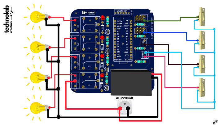
Connection of Appliances & Switches.
Now make the connections of bulb and switches as per this connection diagram.
Testing and Deployment.
- Testing: Rigorously test the system for connectivity, response time, and reliability. Pay special attention to the manual override feature.
- Deployment: Once satisfied, deploy the system. This includes mounting the PCB in a suitable location and ensuring all safety protocols are followed.
Benefits and Future Possibilities

- Enhanced Connectivity: The integration of Wi-Fi and Bluetooth allows for remote control and monitoring, a significant upgrade from the old system.
- Scalability: This approach opens up opportunities to expand the system to include more devices and sensors.
- Customization: The Arduino IoT Cloud platform allows for extensive customization to suit individual needs.
Conclusion.
The Arduino Nano ESP32’s launch is a boon for DIY enthusiasts and professionals alike. By upgrading old home-automation systems with this new board, we not only extend the life of our existing hardware but also unlock new capabilities. This project is a testament to the sustainable and evolving nature of IoT and home automation technologies.
")

