4 Node Home-Automation System Using Smallest ESP32.| XIAO ESP32-C3 | Temperature,Humidity & Manual.

4 Node Home-Automation System Using Smallest ESP32.| XIAO ESP32-C3 | Temperature,Humidity & Manual.

4 Node Home-Automation System Using Smallest ESP32.| XIAO ESP32-C3 | Temperature,Humidity & Manual.

Introducton.

  • In the realm of home automation, the integration of compact design and advanced technology has led to remarkable innovations. A prime example of this is a home-automation project that not only allows control of four appliances via a smartphone app and manual switches but also incorporates global remote access and environmental monitoring. This article delves into the technical aspects of this project, focusing on the code that drives it and the capabilities of its core component, the XIAO ESP32C3.

Overview.

  • In this advanced home automation system, users have the flexibility to control up to four appliances using a smartphone app, providing convenience both locally and globally. Additionally, traditional manual switch buttons are integrated for familiar, everyday use. The system also offers the versatility of appliance control through any IR remote. Beyond control functions, it enables real-time monitoring of temperature and humidity directly on your smartphone, ensuring a seamless and integrated smart home experience.

  • Smartphone App Control.

  • Manual Switch Control.

  • IR Remote Control.

  • Temperature & Humidity Monitoring.

Overview of the Home Automation PCB.

This home automation system is designed around a PCB, roughly the size of a credit card, making it highly integrable within any home environment.

Key features of this PCB include:
  • Onboard Fuse: Ensures overload and short-circuit protection.

  • High-Duty Terminal Connector: Provides spark-free operation and heat protection.

JST Connector: for Connecting DHT Sensor, IR Receiver and Manual Switches.

XIAO ESP32C3: The ‘brain’ of the system, known for its compactness and efficiency.

XIAO ESP32C3:Smallest ESP32 Board.

The Xiao ESP32C3 board, developed by Seeed Studio, is a compact and powerful IoT mini development board. It is based on the Espressif ESP32-C3 WiFi/Bluetooth dual-mode chip, which is a 32-bit RISC-V CPU. This CPU includes an FPU (Floating Point Unit) for 32-bit single-precision arithmetic, providing robust computing power. The board stands out for its excellent radio frequency performance, supporting IEEE 802.11 b/g/n WiFi and Bluetooth 5 (LE) protocols. An external antenna is included to enhance signal strength for wireless applications.

Design and Features

  • Form Factor: The board boasts a small and exquisite form-factor with a single-sided surface-mountable design.
  • Interfaces: It is equipped with 11 digital I/O that can function as PWM pins, 4 analog I/O ADC pins, and supports four serial interfaces including UART, I2C, and SPI.
  • Compatibility: Fully compatible with the Grove Shield for Seeeduino XIAO and Seeeduino XIAO Expansion board, with the exception of the SWD spring contacts.
  • Performance: Positioned as a high-performance, low-power, cost-effective IoT mini development board, it is ideal for low-power IoT and wireless wearable applications.

Technical Specifications

  • CPU: ESP32-C3, 32-bit RISC-V single-core processor operating at up to 160 MHz.
  • Wi-Fi: Complete Wi-Fi subsystem complying with IEEE 802.11b/g/n protocol.
  • Bluetooth: Supports Bluetooth 5 and Bluetooth mesh.
  • Power Efficiency: Ultra-low power consumption with about 43µA in deep sleep mode.
  • Memory: 400KB of SRAM and 4MB of onboard flash memory.
  • Size: Ultra-small (20×17.5mm), suitable for wearable devices and small projects.
  • Security: Features cryptographic hardware accelerators supporting AES-128/256, Hash, RSA, HMAC, digital signature, and secure boot.
  • Battery Management: Includes a battery charging chip for lithium battery charge and discharge management.
  • Low Cost: WIFI/BLE dual mode development board for only $4.99.

The XIAO ESP32C3’s capabilities are well-documented in its Getting Started Guidewhich offers insights into its functionalities and potential applications.

Elevate Your Innovations with Seeed Studio Fusion.

Blynk Cloud Configuration.

To create devices on the Blynk dashboard, you typically need to follow these general steps:
  • Sign Up/Login: First, you need to create an account on Blynk or log in if you already have one.

Access the Dashboard: Once logged in, navigate to the developer zone where you can manage and create new templates.

Click on “+ New Template”  then give the name of your template on which your project is , then select the hardware type in my case it is ESP32, and connection type is WIFI….. after that click on done button, and you have successfully create the template for  your project.

  • Now click on data streams then new data-streams select virtual pin.
  • Give the name of data-streams, give any conventional name you want.
  • Select the pin on which you want to control your relay , I am selecting virtual Pin V1 for button 1, &  select Datatype as Integer.
  • In similar way create 3 more data stream as we need to control four relays in our project, and thier virtual Pin will be V2, V3, V4 for button 2 , button 3 , button 4 respectivily.
  • A fifth datastream for button “all_off” and the virtual Pin will be V5.
  • We need two more data stream for temperature and humidity, that will connected to Virtual Pin V6 & V7.
  • For temperature datatype will be double, Select the unit as degree Celsius.
  • Min. Value is “0” and Max. Value will be “50”.
  • For humidity datatype will be double, Select the unit as percentage.
  • Min. Value is “0″ and Max. Value will be “100“.
  • After creating all the datastreams , Click on save button to save all the configurations.

Create a New Device:

  • Select the option device, then Click on “+ New Devices”
  • Choose option “from template”, and select the template that you have created a bit ago and then click on create button.

  •  After creating device, you can configure its settings, such as data streams, triggers, and other IoT functionalities, and also you will get BLYNK TEMPLATE ID , BLYNK TEMPLATE NAME , BLYNK AUTH TOKEN, that we need in code , so keep these datials safe.

Code.

Click here to download the code.

/**********************************************************************************
 *  
 *  Preferences--> Aditional boards Manager URLs : 
 *  https://raw.githubusercontent.com/espressif/arduino-esp32/gh-pages/package_esp32_dev_index.json
 *  
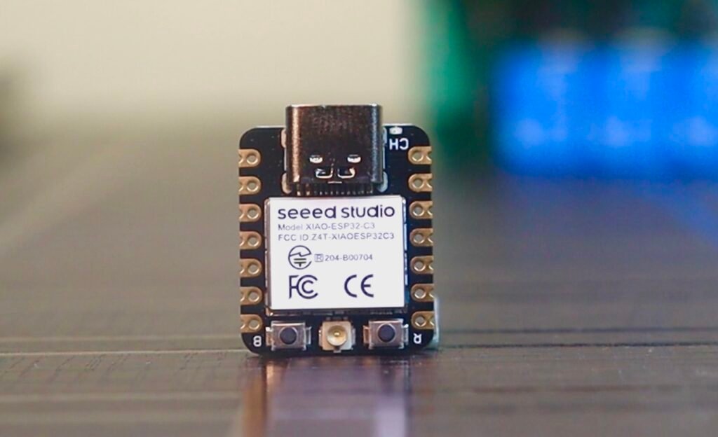
 *  Download Board ESP32 (2.0.5): https://github.com/espressif/arduino-esp32
 *
 *  Download the libraries 
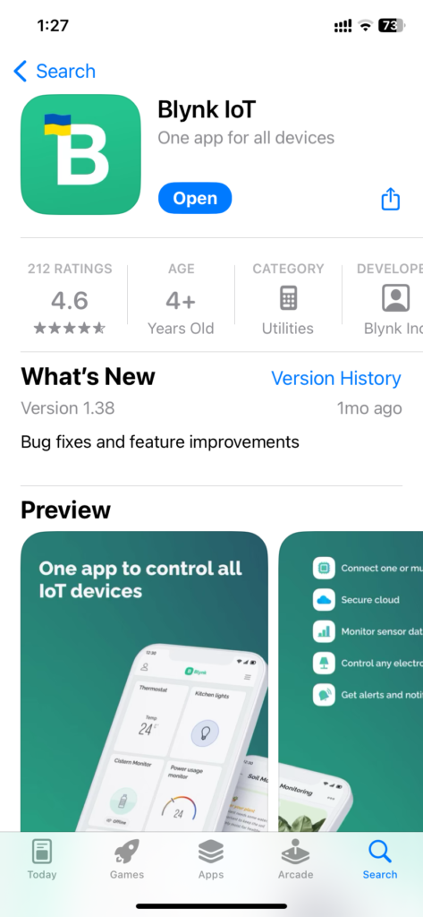
 *  Blynk Library (1.1.0):  https://github.com/blynkkk/blynk-library
 *  IRremote Library (3.6.1): https://github.com/Arduino-IRremote/Arduino-IRremote
 *  DHT Library (1.4.4): https://github.com/adafruit/DHT-sensor-library
 **********************************************************************************/

/* Fill-in your Template ID (only if using Blynk.Cloud) */
#define BLYNK_TEMPLATE_ID "xxxxxxxxxxxxxxxxxxxxxxx"
#define BLYNK_TEMPLATE_NAME "xxxxxxxxxxxxxxxxxxxxxxxxx"
#define BLYNK_AUTH_TOKEN "xxxxxxxxxxxxxxxxxxxxxxxxx"

// Your WiFi credentials.
// Set password to "" for open networks.
char ssid[] = "XXXXXXXXXX";
char pass[] = "XXXXXXXXXX";

//Update the HEX code of IR Remote buttons 0x<HEX CODE>
#define IR_Button_1   0x2880
#define IR_Button_2   0x2886
#define IR_Button_3   0x2885
#define IR_Button_4   0x2883
#define IR_All_Off    0x289E


//#define BLYNK_PRINT Serial
#include <WiFi.h>
#include <WiFiClient.h>
#include <BlynkSimpleEsp32.h>
#include <IRremote.h>
#include <DHT.h>  
#include <Preferences.h>

Preferences pref;

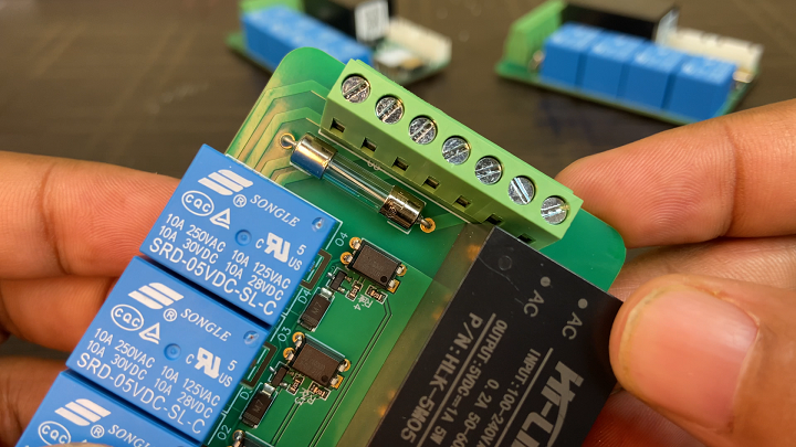
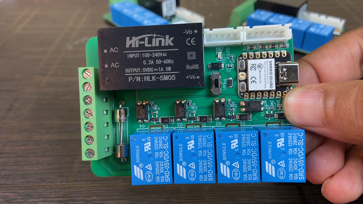
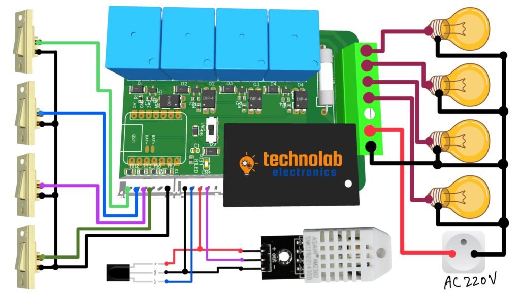
// define the GPIO connected with Relays and switches
#define RelayPin1 D10  
#define RelayPin2 D9  
#define RelayPin3 D8  
#define RelayPin4 D7  

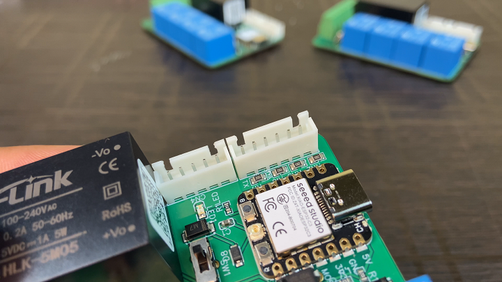
#define SwitchPin1 D1  
#define SwitchPin2 D2  
#define SwitchPin3 D3  
#define SwitchPin4 D4  

#define wifiLed   D0   

#define IR_RECV_PIN   D5  //(IR receiver pin)
#define DHTPIN        D6  // (pin connected with DHT)

//Change the virtual pins according the rooms
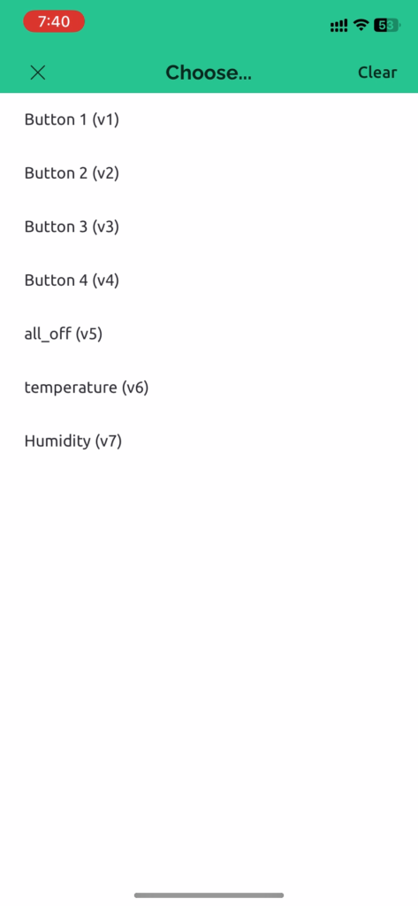
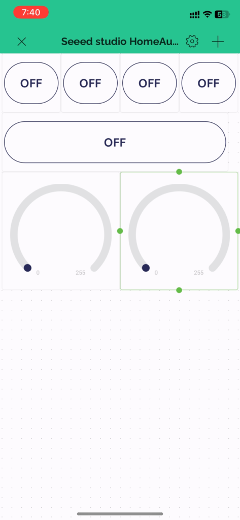
#define VPIN_BUTTON_1    V1 
#define VPIN_BUTTON_2    V2
#define VPIN_BUTTON_3    V3 
#define VPIN_BUTTON_4    V4
#define VPIN_BUTTON_C    V5
#define VPIN_TEMPERATURE V6
#define VPIN_HUMIDITY    V7

// Uncomment whatever type you're using!
#define DHTTYPE DHT11     // DHT 11
//#define DHTTYPE DHT22   // DHT 22, AM2302, AM2321
//#define DHTTYPE DHT21   // DHT 21, AM2301

// Relay State
bool toggleState_1 = LOW; //Define integer to remember the toggle state for relay 1
bool toggleState_2 = LOW; //Define integer to remember the toggle state for relay 2
bool toggleState_3 = LOW; //Define integer to remember the toggle state for relay 3
bool toggleState_4 = LOW; //Define integer to remember the toggle state for relay 4

// Switch State
bool SwitchState_1 = LOW;
bool SwitchState_2 = LOW;
bool SwitchState_3 = LOW;
bool SwitchState_4 = LOW;

int wifiFlag = 0;
float temperature1 = 0;
float humidity1   = 0;

IRrecv irrecv(IR_RECV_PIN);
decode_results results;

DHT dht(DHTPIN, DHTTYPE);

char auth[] = BLYNK_AUTH_TOKEN;

BlynkTimer timer;

// When App button is pushed - switch the state

BLYNK_WRITE(VPIN_BUTTON_1) {
  toggleState_1 = param.asInt();
  digitalWrite(RelayPin1, toggleState_1);
  pref.putBool("Relay1", toggleState_1);
}

BLYNK_WRITE(VPIN_BUTTON_2) {
  toggleState_2 = param.asInt();
  digitalWrite(RelayPin2, toggleState_2);
  pref.putBool("Relay2", toggleState_2);
}

BLYNK_WRITE(VPIN_BUTTON_3) {
  toggleState_3 = param.asInt();
  digitalWrite(RelayPin3, toggleState_3);
  pref.putBool("Relay3", toggleState_3);
}

BLYNK_WRITE(VPIN_BUTTON_4) {
  toggleState_4 = param.asInt();
  digitalWrite(RelayPin4, toggleState_4);
  pref.putBool("Relay4", toggleState_4);
}

BLYNK_WRITE(VPIN_BUTTON_C) {
  all_SwitchOff();
}

void checkBlynkStatus() { // called every 2 seconds by SimpleTimer

  bool isconnected = Blynk.connected();
  if (isconnected == false) {
    wifiFlag = 1;
    Serial.println("Blynk Not Connected");
    digitalWrite(wifiLed, LOW);
  }
  if (isconnected == true) {
    wifiFlag = 0;
    digitalWrite(wifiLed, HIGH);
    //Serial.println("Blynk Connected");
  }
}

BLYNK_CONNECTED() {
  // update the latest state to the server
  Blynk.virtualWrite(VPIN_BUTTON_1, toggleState_1);
  Blynk.virtualWrite(VPIN_BUTTON_2, toggleState_2);
  Blynk.virtualWrite(VPIN_BUTTON_3, toggleState_3);
  Blynk.virtualWrite(VPIN_BUTTON_4, toggleState_4);

  Blynk.syncVirtual(VPIN_TEMPERATURE);
  Blynk.syncVirtual(VPIN_HUMIDITY);
}

void readSensor(){
  
  float h = dht.readHumidity();
  float t = dht.readTemperature(); // or dht.readTemperature(true) for Fahrenheit
  
  if (isnan(h) || isnan(t)) {
    Serial.println("Failed to read from DHT sensor!");
    return;
  }
  else {
    humidity1 = h;
    temperature1 = t;
   Serial.println(temperature1);
   Serial.println(humidity1);
  }  
}

void sendSensor()
{
  readSensor();
  // You can send any value at any time.
  // Please don't send more that 10 values per second.
  Blynk.virtualWrite(VPIN_HUMIDITY, humidity1);
  Blynk.virtualWrite(VPIN_TEMPERATURE, temperature1);
}

void manual_control()
{
  if (digitalRead(SwitchPin1) == LOW && SwitchState_1 == LOW) {
    digitalWrite(RelayPin1, LOW);
    toggleState_1 = HIGH;
    SwitchState_1 = HIGH;
    pref.putBool("Relay1", toggleState_1);
    Blynk.virtualWrite(VPIN_BUTTON_1, !toggleState_1);
    Serial.println("Switch-1 on");
  }
  if (digitalRead(SwitchPin1) == HIGH && SwitchState_1 == HIGH) {
    digitalWrite(RelayPin1, HIGH);
    toggleState_1 = LOW;
    SwitchState_1 = LOW;
    pref.putBool("Relay1", toggleState_1);
    Blynk.virtualWrite(VPIN_BUTTON_1, !toggleState_1);
    Serial.println("Switch-1 off");
  }
  if (digitalRead(SwitchPin2) == LOW && SwitchState_2 == LOW) {
    digitalWrite(RelayPin2, LOW);
    toggleState_2 = HIGH;
    SwitchState_2 = HIGH;
    pref.putBool("Relay2", toggleState_2);
    Blynk.virtualWrite(VPIN_BUTTON_2, !toggleState_2);
    Serial.println("Switch-2 on");
  }
  if (digitalRead(SwitchPin2) == HIGH && SwitchState_2 == HIGH) {
    digitalWrite(RelayPin2, HIGH);
    toggleState_2 = LOW;
    SwitchState_2 = LOW;
    pref.putBool("Relay2", toggleState_2);
    Blynk.virtualWrite(VPIN_BUTTON_2, !toggleState_2);
    Serial.println("Switch-2 off");
  }
  if (digitalRead(SwitchPin3) == LOW && SwitchState_3 == LOW) {
    digitalWrite(RelayPin3, LOW);
    toggleState_3 = HIGH;
    SwitchState_3 = HIGH;
    pref.putBool("Relay3", toggleState_3);
    Blynk.virtualWrite(VPIN_BUTTON_3, !toggleState_3);
    Serial.println("Switch-3 on");
  }
  if (digitalRead(SwitchPin3) == HIGH && SwitchState_3 == HIGH) {
    digitalWrite(RelayPin3, HIGH);
    toggleState_3 = LOW;
    SwitchState_3 = LOW;
    pref.putBool("Relay3", toggleState_3);
    Blynk.virtualWrite(VPIN_BUTTON_3, !toggleState_3);
    Serial.println("Switch-3 off");
  }
  if (digitalRead(SwitchPin4) == LOW && SwitchState_4 == LOW) {
    digitalWrite(RelayPin4, LOW);
    toggleState_4 = HIGH;
    SwitchState_4 = HIGH;
    pref.putBool("Relay4", toggleState_4);
    Blynk.virtualWrite(VPIN_BUTTON_4, !toggleState_4);
    Serial.println("Switch-4 on");
  }
  if (digitalRead(SwitchPin4) == HIGH && SwitchState_4 == HIGH) {
    digitalWrite(RelayPin4, HIGH);
    toggleState_4 = LOW;
    SwitchState_4 = LOW;
    pref.putBool("Relay4", toggleState_4);
    Blynk.virtualWrite(VPIN_BUTTON_4, !toggleState_4);
    Serial.println("Switch-4 off");
  }
}    

void ir_remote(){
  if (irrecv.decode(&results)) {
      switch(results.value){
          case IR_Button_1:  
            digitalWrite(RelayPin1, toggleState_1);
            toggleState_1 = !toggleState_1;
            pref.putBool("Relay1", toggleState_1);
            Blynk.virtualWrite(VPIN_BUTTON_1, !toggleState_1);
            delay(100);            
            break;
          case IR_Button_2:  
            digitalWrite(RelayPin2, toggleState_2);
            toggleState_2 = !toggleState_2;
            pref.putBool("Relay2", toggleState_2);
            Blynk.virtualWrite(VPIN_BUTTON_2, !toggleState_2);
            delay(100);            
            break;
          case IR_Button_3:  
            digitalWrite(RelayPin3, toggleState_3);
            toggleState_3 = !toggleState_3;
            pref.putBool("Relay3", toggleState_3);
            Blynk.virtualWrite(VPIN_BUTTON_3, !toggleState_3);
            delay(100);            
            break;
          case IR_Button_4:  
            digitalWrite(RelayPin4, toggleState_4);
            toggleState_4 = !toggleState_4;
            pref.putBool("Relay4", toggleState_4);
            Blynk.virtualWrite(VPIN_BUTTON_4, !toggleState_4);
            delay(100);            
            break;
          case IR_All_Off:
            all_SwitchOff();  
            break;
          default : break;         
        }   
        //Serial.println(results.value, HEX);    
        irrecv.resume();   
  } 
}

void all_SwitchOff(){
  toggleState_1 = LOW; digitalWrite(RelayPin1, LOW); pref.putBool("Relay1", toggleState_1); Blynk.virtualWrite(VPIN_BUTTON_1, toggleState_1); delay(100);
  toggleState_2 = LOW; digitalWrite(RelayPin2, LOW); pref.putBool("Relay2", toggleState_2); Blynk.virtualWrite(VPIN_BUTTON_2, toggleState_2); delay(100);
  toggleState_3 = LOW; digitalWrite(RelayPin3, LOW); pref.putBool("Relay3", toggleState_3); Blynk.virtualWrite(VPIN_BUTTON_3, toggleState_3); delay(100);
  toggleState_4 = LOW; digitalWrite(RelayPin4, LOW); pref.putBool("Relay4", toggleState_4); Blynk.virtualWrite(VPIN_BUTTON_4, toggleState_4); delay(100);
  Blynk.virtualWrite(VPIN_HUMIDITY, humidity1);
  Blynk.virtualWrite(VPIN_TEMPERATURE, temperature1);
}

void getRelayState()
{
  //Serial.println("reading data from NVS");
  toggleState_1 = pref.getBool("Relay1", 0);
  digitalWrite(RelayPin1, !toggleState_1); 
  Blynk.virtualWrite(VPIN_BUTTON_1, toggleState_1);
  delay(200);
  toggleState_2 = pref.getBool("Relay2", 0);
  digitalWrite(RelayPin2, !toggleState_2); 
  Blynk.virtualWrite(VPIN_BUTTON_2, toggleState_2);
  delay(200);
  toggleState_3 = pref.getBool("Relay3", 0);
  digitalWrite(RelayPin3, !toggleState_3); 
  Blynk.virtualWrite(VPIN_BUTTON_3, toggleState_3);
  delay(200);
  toggleState_4 = pref.getBool("Relay4", 0);
  digitalWrite(RelayPin4, !toggleState_4); 
  Blynk.virtualWrite(VPIN_BUTTON_4, toggleState_4);
  delay(200); 
}

void setup()
{
  Serial.begin(9600);
  pref.begin("Relay_State", false);
  
  pinMode(RelayPin1, OUTPUT);
  pinMode(RelayPin2, OUTPUT);
  pinMode(RelayPin3, OUTPUT);
  pinMode(RelayPin4, OUTPUT);

  pinMode(wifiLed, OUTPUT);

  pinMode(SwitchPin1, INPUT_PULLUP);
  pinMode(SwitchPin2, INPUT_PULLUP);
  pinMode(SwitchPin3, INPUT_PULLUP);
  pinMode(SwitchPin4, INPUT_PULLUP);

  //During Starting all Relays should TURN OFF
  digitalWrite(RelayPin1, !toggleState_1);
  digitalWrite(RelayPin2, !toggleState_2);
  digitalWrite(RelayPin3, !toggleState_3);
  digitalWrite(RelayPin4, !toggleState_4);

  digitalWrite(wifiLed, LOW);
  
  irrecv.enableIRIn(); // Enabling IR sensor
  dht.begin();    // Enabling DHT sensor

  //Blynk.begin(auth, ssid, pass);
  WiFi.begin(ssid, pass);
  timer.setInterval(2000L, checkBlynkStatus); // check if Blynk server is connected every 2 seconds
  timer.setInterval(1000L, sendSensor); // Sending Sensor Data to Blynk Cloud every 1 second
  Blynk.config(auth);
  delay(1000);

  getRelayState(); //fetch data from NVS Flash Memory
}

void loop()
{ 
  manual_control();
  ir_remote(); //IR remote Control
  Blynk.run();
  timer.run();
}

 Here’s a breakdown of its key components and functionalities:

1.Blynk Configuration:

  •    `#define BLYNK_TEMPLATE_ID` and `#define BLYNK_TEMPLATE_NAME`: These lines define the template ID and name for the Blynk project.
  •    `#define BLYNK_AUTH_TOKEN`: This is the authentication token generated by Blynk, used to connect your hardware to the Blynk Cloud.

2. WiFi Credentials:

  •    `char ssid[]`and `char pass[]`: These arrays store your WiFi network’s SSID and password.

3. IR Remote Button Codes:

  •    `#define IR_Button_1`, etc.: These define the hex codes for the IR remote control buttons.

4. Pin Configuration:

  •    `#define RelayPin1`, etc.: These define which GPIO pins on the ESP32 are connected to the relays.
  •    `#define SwitchPin1`, etc.: These define GPIO pins connected to physical switches.

5. Virtual Pins for Blynk App:

  •    `#define VPIN_BUTTON_1`, etc.: These define virtual pins in the Blynk app to control and monitor different aspects of the system.

6.DHT Sensor Type:

  •    `#define DHTTYPE DHT11`: This line sets the type of DHT sensor used (DHT11, DHT22, or DHT21).

7.Global Variables:

  •    `bool toggleState_1`, etc.: These variables store the current state (on/off) of each relay.
  •    `bool SwitchState_1`, etc.: These variables store the state of each physical switch.

8. Blynk Functions:

  •    `BLYNK_WRITE(VPIN_BUTTON_1)`: This function is called whenever the corresponding virtual button in the Blynk app is pressed.

9.Setup Function:

  •   `void setup()`: This function runs once when the ESP32 starts. It initializes serial communication, sets pin modes, initializes the DHT sensor, connects to WiFi, and sets up Blynk.

10.Main Loop:

  •   `void loop()`: This is the main loop that runs continuously. It checks for manual control inputs, IR remote inputs, and keeps the Blynk connection alive.

11. Sensor Reading and Data Transmission:

  •     `void readSensor()` and `void sendSensor()`: These functions are responsible for reading data from the DHT sensor and sending it to the Blynk app.

12.Manual and IR Remote Control Functions:

  •   `void manual_control()` and `void ir_remote()`: These functions allow for control of the system through physical switches and an IR remote.

13.Utility Functions:

  •     `void all_SwitchOff()` and `void getRelayState()`: These functions provide additional functionality like turning off all relays and fetching the last known state of the relays from storage.

Blynk: Mobile Dashboard Configuration.

Download and Install the Blynk App

  • Download the Blynk App: Go to the App Store (for iOS devices) or Google Play Store (for Android devices).
  • Install the App: Search for “Blynk” and install the app on your mobile device.

Set Up Your Account

  • Open the App: Launch the Blynk app on your device.
  • Login: log in Using the same credentials the one you have used in web-dashboard.

 Access the Dashboard

  • Navigate to the Device: Once logged in, you will be taken to the main device that you have created on the web-dashboard.
  • Set Up Widgets: Tap on the “+” icon , then drag and drop five button widget and two gauge widget to control appliances and monitor the sensor reading respectivily.
  • Assign Virtual Pins: Connect these widgets to virtual pins that correspond to hardware’s code and for buttons widgets select the button type as switch.

  • Test Your Setup: Interact with the widgets in the app and observe if the hardware responds as expected.
  • Monitor and Modify: You can monitor the status of your devices and modify settings or widgets as needed.

Connection Diagram.

Connect all your Appliances, Switches and Sensors as per the connection diagram shown below.

Now you’ve successfully set up your Blynk cloud configuration, written and uploaded the code to your devices, configured the Blynk smartphone app, and connected all your hardware components like bulbs, switches, and sensors. Here’s what you can do next:

1. Test Your Setup

  • Operate the Devices: Use the Blynk app to control the connected devices. For example, turn the bulb on and off, activate switches, and monitor sensor readings.
  • Check for Responsiveness: Ensure that the devices respond correctly to the app commands.
  • Monitor Sensor Data: If you have sensors connected, check if their data is being accurately reported in the app.

 2. Troubleshoot if Necessary

  • Identify Issues: If something isn’t working as expected, try to identify where the issue lies – whether it’s in the hardware, the code, the Blynk app configuration, or the network connection.
  • Consult Documentation: Refer to Blynk’s documentation or forums for troubleshooting tips.
  • Check Connections: Ensure all physical connections are secure and the devices are powered correctly.

3. Refine Your Project

  • Adjust the Code: You might want to tweak your code for better performance or to add new features.
  • Update the App Interface: Modify the Blynk app dashboard if needed, such as rearranging controls or changing their appearance for better usability.
  • Expand Functionality: Consider adding more devices or sensors to your project.

4. Monitor and Maintain

  • Regular Checks: Regularly check the system to ensure it’s functioning correctly.
  • Firmware Updates: Keep your device firmware and Blynk app updated.

 5. Document and Backup

  • Keep Records: Document your setup and configurations for future reference.
  • Backup Configurations: Backup your Blynk project settings and device code.

Conclusion.

This home automation project represents a significant leap in DIY smart home technology. It leverages the power of the XIAO ESP32C3, bringing sophisticated control and monitoring capabilities into a compact, user-friendly package. The combination of smartphone integration, environmental sensing, and traditional control methods makes it a versatile and innovative solution for modern homes.

Interested individuals can further explore the technical specifics and potential extensions of this project by referring to the detailed code and the XIAO ESP32C3 documentation. This project not only demonstrates the capabilities of current IoT technologies but also opens doors for future advancements in home automation.

Video Tutorial.

One thought on “4 Node Home-Automation System Using Smallest ESP32.| XIAO ESP32-C3 | Temperature,Humidity & Manual.

Leave a Reply

Your email address will not be published. Required fields are marked *

Back To Top