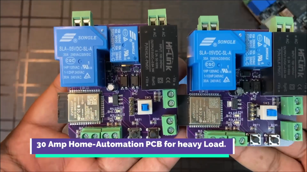
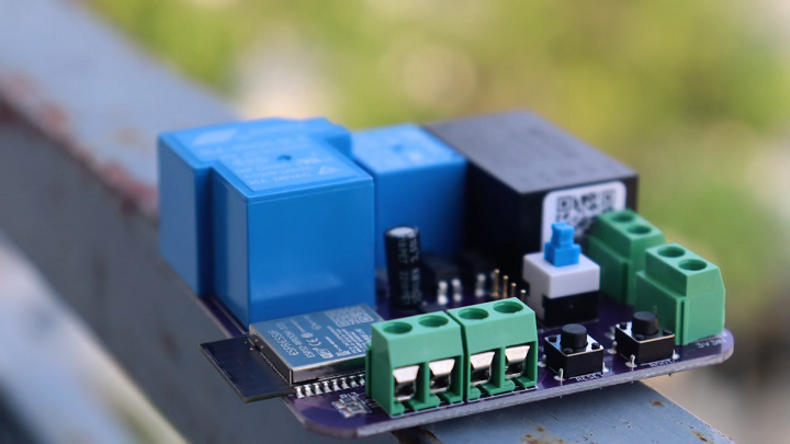
In this article I am going to introduce my newly designed 30amp home-automation PCB.
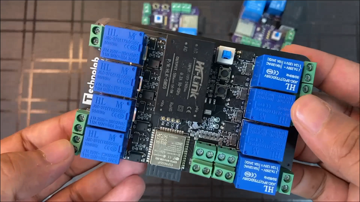
I have also designed lot other home-automation PCBs, like 2 node , 4 node and 8 node home-automation PCBs.
These PCBs are fully tested and works very well These PCBs are best for home-automation system, But these PCBs could handle only Upto 10 amp load, So we can only use this PCBs for small load appliances like light bulb, televisions which consume less power,
But if we want to automate heavy load appliances like air conditioners, washing machines, geyser then in that case , we couldn’t connect to these PCBs.
These PCBs will not handle such heavy load and eventually the relay will burn out.
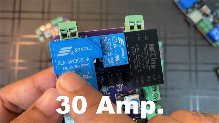
So to solve this problem, I have design brand new home-automation PCB which can easily handle Upto 30amp load.
And most of the heavy load appliances that we used in our homes consumes current under 30 amp, So this PCBs is perfect for those appliances.
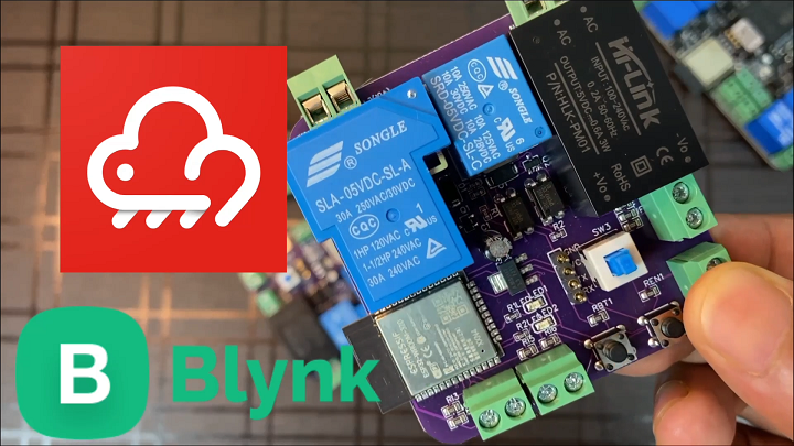
This PCB is compatible with all the popular IOT platform like BLYNK, ESP-RAINMAKER.
In this way we can easily integrate this PCB with Alexa and google assistant.
And apart from this , we can also give manual input to this PCB and also we can connect via Bluetooth to control the appliances from smartphone application in local area network.
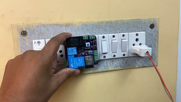
And the size of this PCB is very small. and can easily fits inside the electrical switch board.
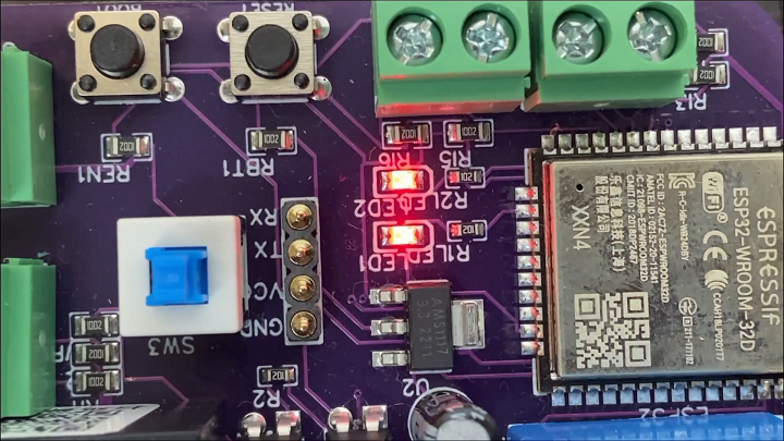
And there is two onboards LEDs , which we can use in many ways, like for testing code, WIFI indicator.
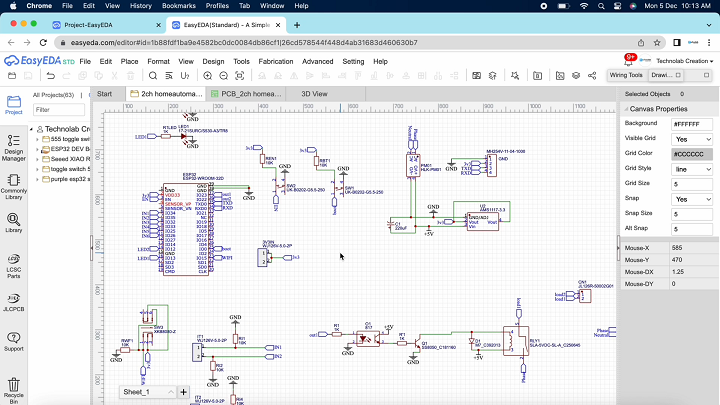
PCB Design.
This is the Schematic of PCBs. If you want Your own custom designed PCBs, Then you can download this schematic.
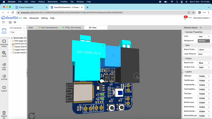
After making the Schematic, Convert it into PCB, Arrange and place all the components in desirable places, Once the layout is ready route the wiring and complete the design of PCB.
After The completion of PCB design, You need to download three files which will required during PCB order. These files are BOM, Gerber and CPL that is pick and place file.
Ordering the PCBs at JLCPCB.
This project is sponsored by JLCPCB. JLCPCB is a full feature Printed Circuit Board manufacturing service.
Turn your DIY breadboard circuits into professional PCBs– get 10 boards for approximately $5 + shipping (which will vary depending on your country).
Once you have your Gerber files, you can order the PCB. Follow the next steps.
1. Download the Gerber files –click here to download the.zip file.
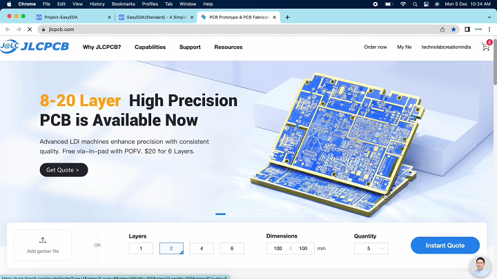
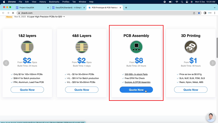
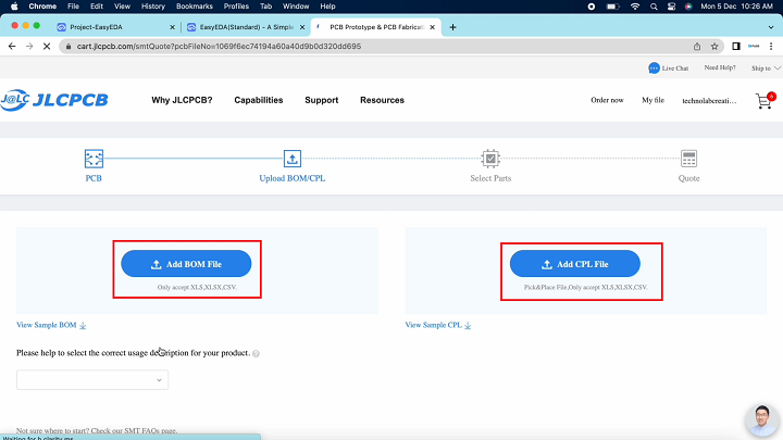
2. Go to JLCPCB website and Click on Quote Now button under PCB assembly.
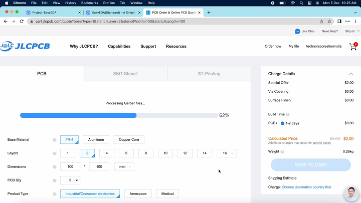
3.Upload the Gerber file you downloaded in the last step. Upload the.zip file or you can also drag and drop the Gerber files.
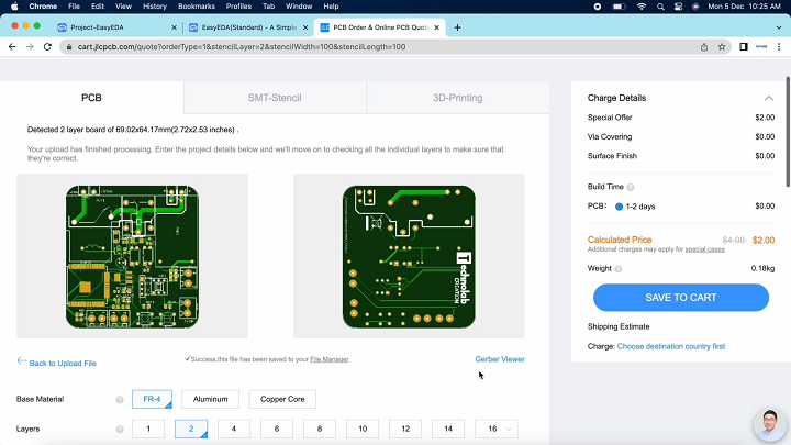
After uploading the zip file, you’ll see a success message at the bottom if the file is successfully uploaded. You can review the PCB in the Gerber viewer to make sure everything is good.
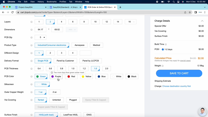
JLCPCB can grab all the PCB details and automatically fills them for you.
Select the PCB quantity and color masking of PCB by your self. I am selecting white color.
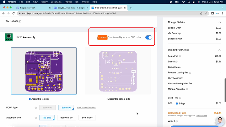
Scroll down below and select for PCB assembly.
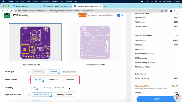
Here you have to select on which Side you want to PCB assembly top side or bottom side or on both side. In my case I want only on top sides. After that click on confirm button.
For PCB assembly we need two more files, One is BOM that is bill of material and the second one is CPL that is pick and place file, Upload these two files one by one.
After that click on next button.
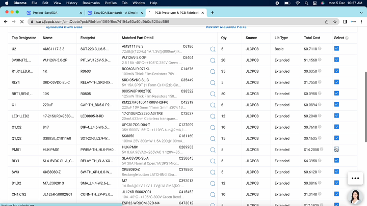
All the components were shown here that are to be assembled. In case if you want to not assemble any particular component then you can de-select that components.
After checking all the components click on next button.
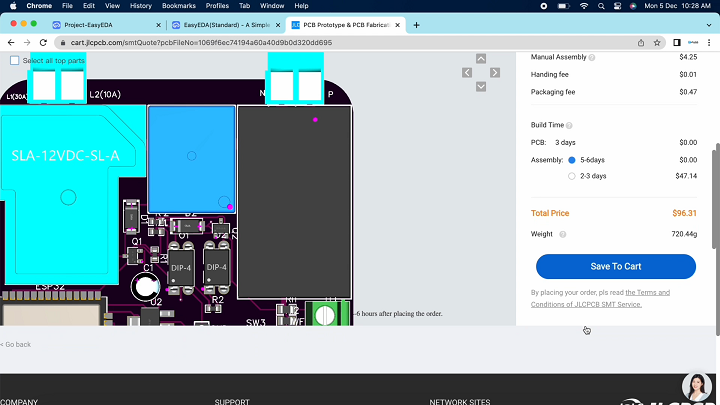
Here you will see a computer version of components placement which seems not accurate. This is only for reference purpose. Now click on save to cart to complete your order.
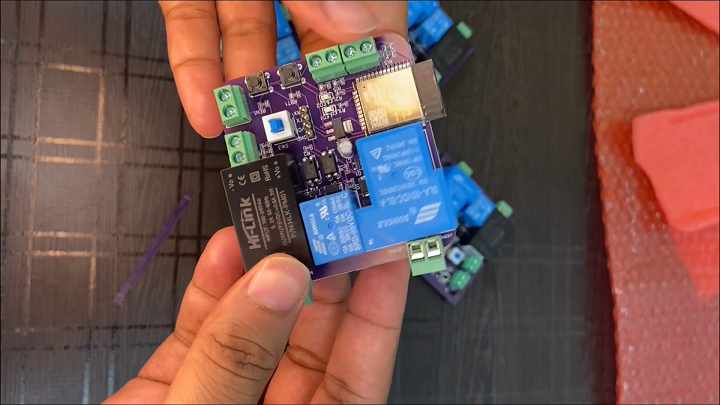
After seven days, PCBs arrived at my place. As usual the quality of PCB is very premium, and the Components are soldered very well.
Traces are perfect, silkscreen is fine, Green color PCB masking looks very beautiful and PCBs look pretty professional.
Code.
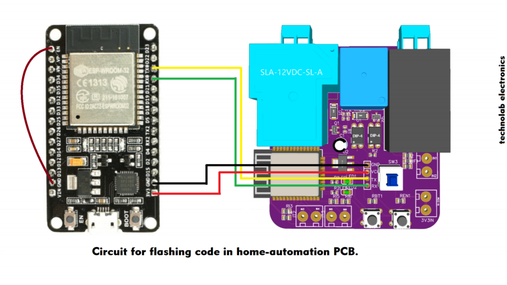
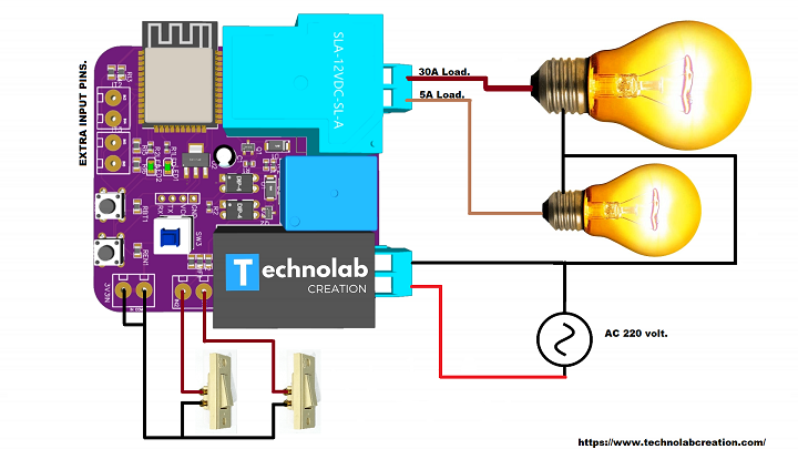
To upload the code into ESP32 chip I will use esp32 development board , Connect the PCB to esp32 board as per this Circuit diagram.
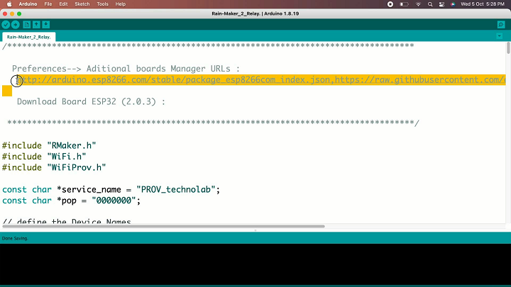
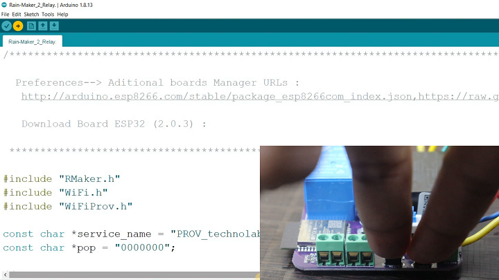
This is the code for our todays home automation project, before you upload the code first you need to update the esp32 boards library in your Arduino ide.
This is the code for our todays home automation project, before you upload the code first you need to update the esp32 boards library in your Arduino ide.
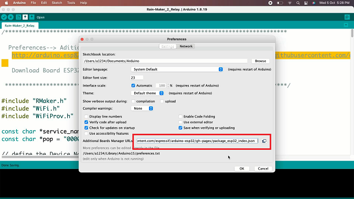
Open Arduino preference and paste the copied link.
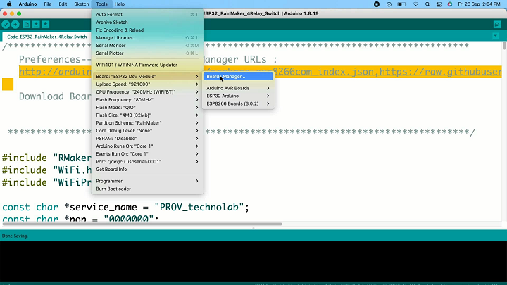
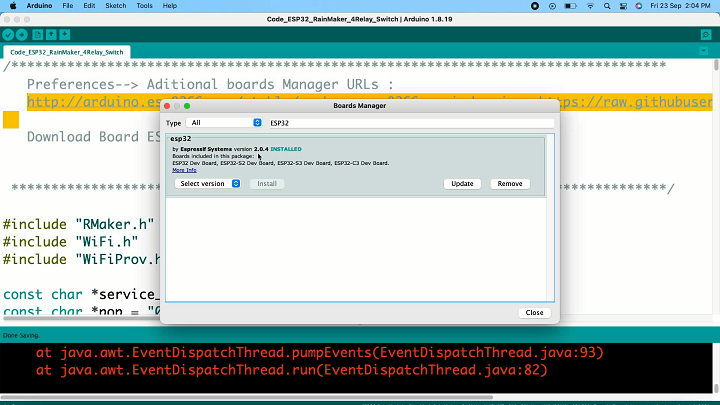
Now go-to tools and then click on board manager,
Search for esp32, here you have to install this latest esp32 boards in your Arduino IDE, Close this window after Installation.
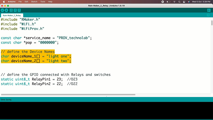
Now in the code, I have define the names of devices….light 1, light 2 like that…..you can give any name you want.
I have define the pins for relays and switches, If you are using my PCB then no need to change anything. Just upload the code as it is…..
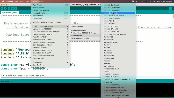
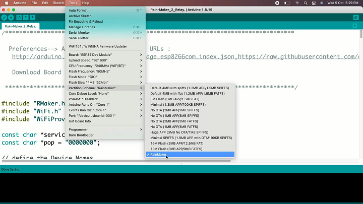
Now Go-to tools and select the right board, that is esp32 dev module.
Now click on partition scheme and select rainmaker.
and in the last select the right communication port then click on upload button to upload the code.
After clicking the upload button, on the PCB Press and hold the boot button and press the reset button once to make the module go inside the boot mode.
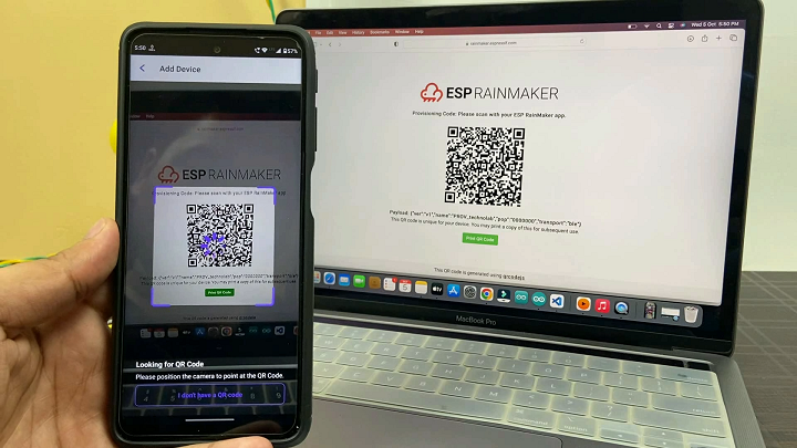
After uploading the code you need to configure the ESP Rain-maker app, but I am skipping this configuration part, because the configuration is same as in 2 channel relay, just check out that article.
you will able to control your heavy load appliances from the smartphone application as well as from the smart speakers.
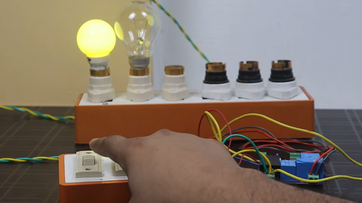
Connection of Appliances & Switches.
Now connect all the switches and appliances as per this connection diagram, here I am using light bulb to demonstrate this project.
After completing all the above setups and configuration, now you able to control your heavy load appliances from smart-speakers, from smart-phone as well from the manual switches.
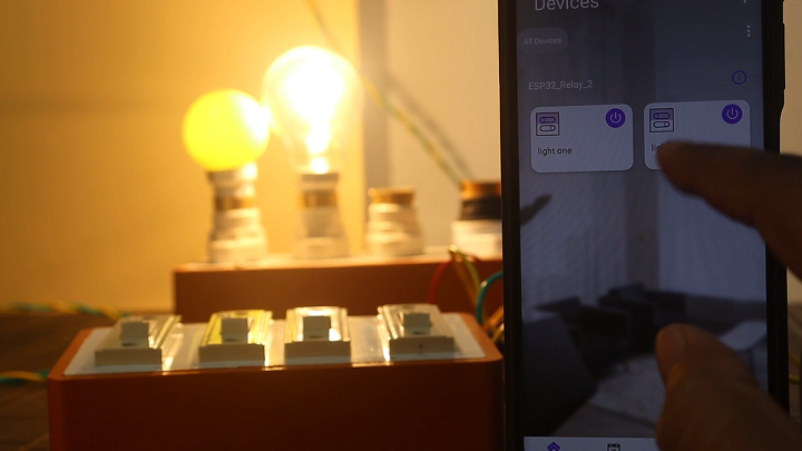
Controlling appliances from ESP Rainmaker App.
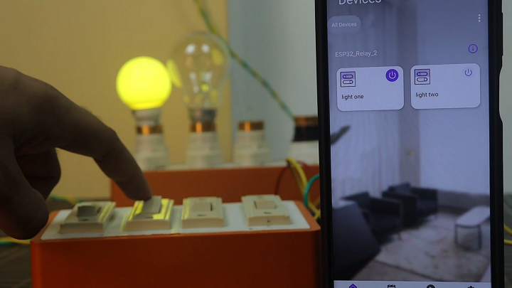
Controlling Appliances from the Manual Switch button.
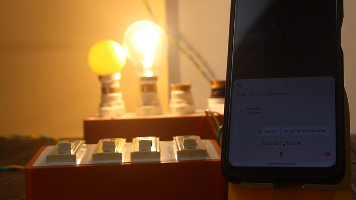
Controlling appliances from Google Assistant and from Alexa.
Conclusion.
As you see can I am able to control the Devices from the manual switch buttons, from giving voice command to Alexa and google assistant.
And apart from this we can also control it through the ESP Rain maker app.
This is the most simple and best home automation project.
You can now control your heavy load appliances from your smartphones as well from smart speakers through voice command.
You can install this PCB in your home or office to make your appliances smart.
If you purchase this PCB you will get a QR code along with this PCB, just scan this QR code with the ESP Rain maker app and easily Integrate the Alexa smart speaker and google assistant to it. And make your device smart.


")

