SIM900A GSM Module and Arduino: Sending and Receiving SMS Using AT Commands
This tutorial is a complete guide to the SIM900 GSM GPRS Shield with the Arduino. Learn how to send and receive SMS using arduino and SIM900A.
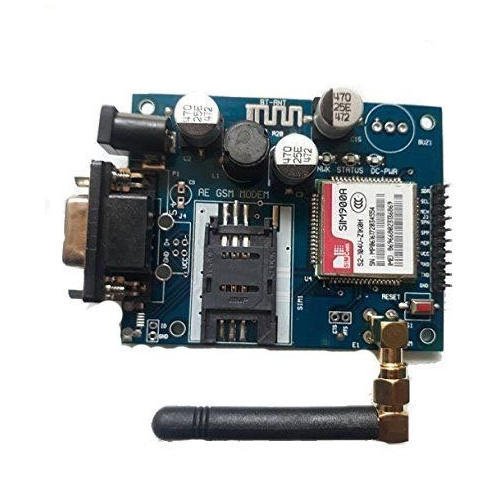
The SIM900A is a complete Dual-band GSM/GPRS solution in a SMT module which can be embedded in the customer applications. Featuring an industry-standard interface, the SIM900A delivers GSM/GPRS 900/1800MHz performance for voice, SMS, Data, and Fax in a small form factor and with low power consumption.
GSM stands for Global System for Mobile Communications and is the global standard for mobile communications.
GPRS stands for General Packet Radio Service. GPRS is a mobile service on the 2G and 3G cellular communication
Applications:
The GSM GPRS shield is particularly useful as it allows to:
Connect to the Internet over GPRS network
Send and receive SMS
Place and receive phones calls
Its capabilities make it perfect for projects with Arduino like:
Remote control of electronic appliances – sending an SMS to turn something on;
Receive notifications – send SMS to your cell phone if movement is detected in your house;
Receive sensor data – send periodic SMS to your cell phone with daily weather data.
Features
Here’s some of the most important features of the shield:
Compatible with Arduino and clones
Based on SIM900 module from SIMCOM
Allows you to send SMS, MMS, GPRS and Audio via UART using AT commands.
It has 12 GPIOs, 2 PWMs and buit-in ADC of the SIM900 module
Quad Band: 850; 900; 1800 and 1900 MHZ, so it should work in all countries with GSM (2G) networks
Control via AT commands
Preliminary steps
Before getting started with your SIM900 GSM GPRS module, you need to consider some aspects about the SIM card and the shield power supply.
GSM coverage
Ensure you have coverage on a GSM 850 MHz, GSM 900 MHz, DCS 1800 MHz or PCS 1900 MHz network. By GSM we mean 2G.
Prepaid SIM Card
We recommend that you use a prepaid plan or a plan with unlimited SMS for testing purposes. Otherwise, if something goes wrong, you may need to pay a huge bill for hundreds of SMS text messages sent by mistake. In this tutorial we’re using a prepaid plan with unlimited SMS.
The shield uses the original SIM card size, not micro or nano.
Getting the right power supply
To power up the shield, it is advisable to use a 5V power supply that can provide 2A as the one shown below
Getting started
1) Insert the SIM card into the SIM card holder – make sure you’ve read the preliminary steps in the previous section.
2) Make sure the antenna is well connected.
Connection with Arduino uno
Arduino uno GSM Module
RX ========> GPIO 10
TX ========> GPIO 9
GND =======> GND
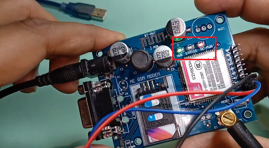
Power the shield using an external 12V & 2amp power supply.
The Status LED will light up and the NetLight LED will blink every 800 ms until it finds the network. When it finds the network, the NetLight LED will start blinking every three seconds.
CODE
Copy and upload this code to your arduino uno board.
 #include <SoftwareSerial.h>

SoftwareSerial mySerial(9, 10);

void setup()
{
  mySerial.begin(9600);   // Setting the baud rate of GSM Module
  Serial.begin(9600);    // Setting the baud rate of Serial Monitor (Arduino)
  delay(100);
}


void loop()
{
  if (Serial.available()>0)
   switch(Serial.read())
  {
    case 's':
      mySerial.println("AT+CMGF=1");    //Sets the GSM Module in Text Mode
     delay(1000);  // Delay of 1 second
     mySerial.println("AT+CMGS=\"+91xxxxxxxxxx\"\r"); // Replace x with mobile number
     delay(1000);
     mySerial.println("Technolab creation");// The SMS text you want to send
     delay(100);
     mySerial.println((char)26);// ASCII code of CTRL+Z for saying the end of sms to  the module
      delay(1000);
      break;


    case 'r':
      mySerial.println("AT+CNMI=2,2,0,0,0"); // AT Command to receive a live SMS
      delay(1000);
      break;
  }

 if (mySerial.available()>0)
   Serial.write(mySerial.read());
}
Sir I need a help from you,
I am using the Same GSM module but as soon as I power it the network led is glowing in red after a min it blinks on every 3 sec on red, on first usage it used to glow in green but from second time onwards it is not glowing in green and I am getting errors in serial monitor. Please help me out , i have used airtel 4g sim in it


I want to learn thanks
as per above information — Compatible with Arduino and clones ..
Can we use above SIM with ESP32 WROOM ?
Yes you can use with ESP32.
Sir I need a help from you,
I am using the Same GSM module but as soon as I power it the network led is glowing in red after a min it blinks on every 3 sec on red, on first usage it used to glow in green but from second time onwards it is not glowing in green and I am getting errors in serial monitor. Please help me out , i have used airtel 4g sim in it
sir the sms is not recieving i have tried for lot times
Thanks for finally talking about > SIM900A GSM Module and Arduino: Sending
and Receiving SMS Using AT Commands < Loved it!
Will it support with arduino mega with same connections
Yes
Amazing! Its truly amazing article, I have got much clear idea about
from this piece of writing.
I enjoy reading through a post that can make people think.
Also, thank you for allowing me to comment!
Hi there, I enjoy reading through your post. I like to write a little
comment to support you.
bro for me its not sending
Thanks for thr great article!
Thank you so much!