

In this post we are going to make a very interesting homeautomation system in which we control our homeappliances by using Amazon-Alexa and we can control it manually.
that is two way controlled homeautomation system,Alexa will work only if we have active wifi , so in case if we don’t have internet or our internet is down , we control our appliances by regular switches as we always do.
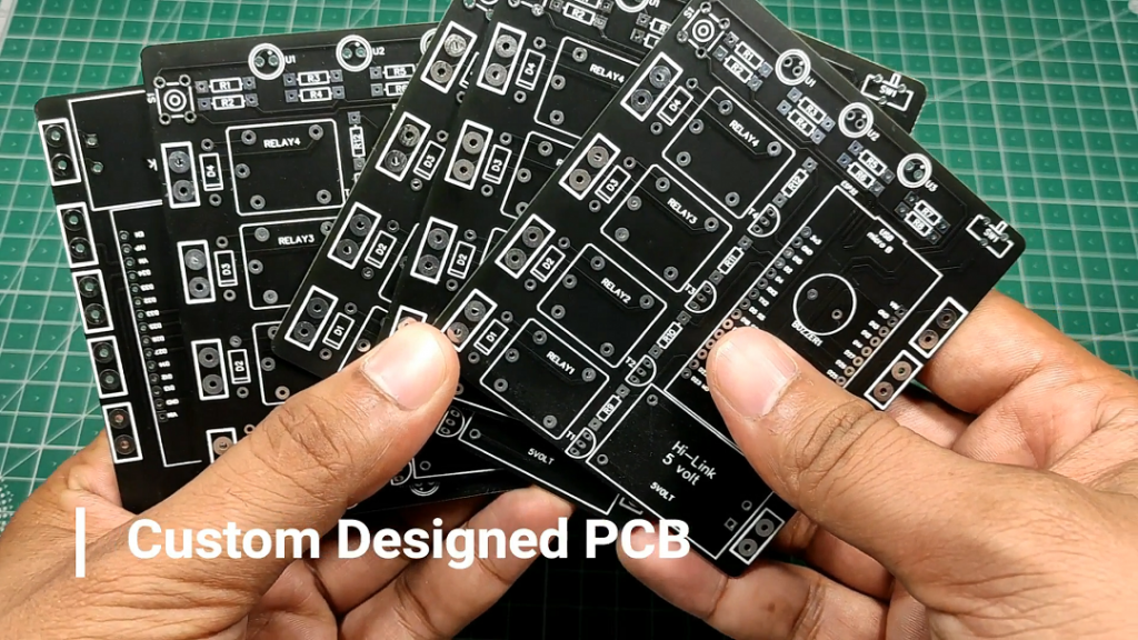
for making of this project we need a coustom made PCB and Alexa smart speaker, and the best part of this project is we don’t need ant third part IOT cloud plateform like BLYNK, SINRIC or IFTTT.
Components Requried
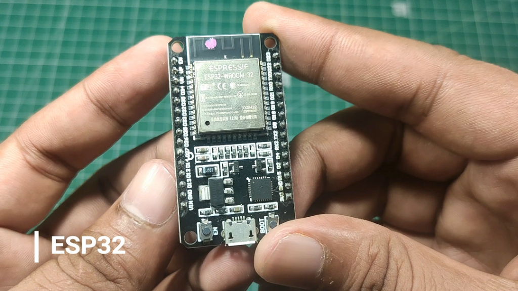
1. ESP32.
2. Highlink AC to DC convertor(HLK-PMO1).
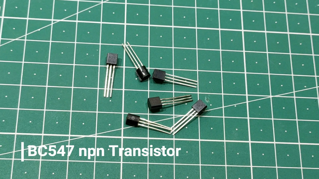
3. BC547 npn Transistor.
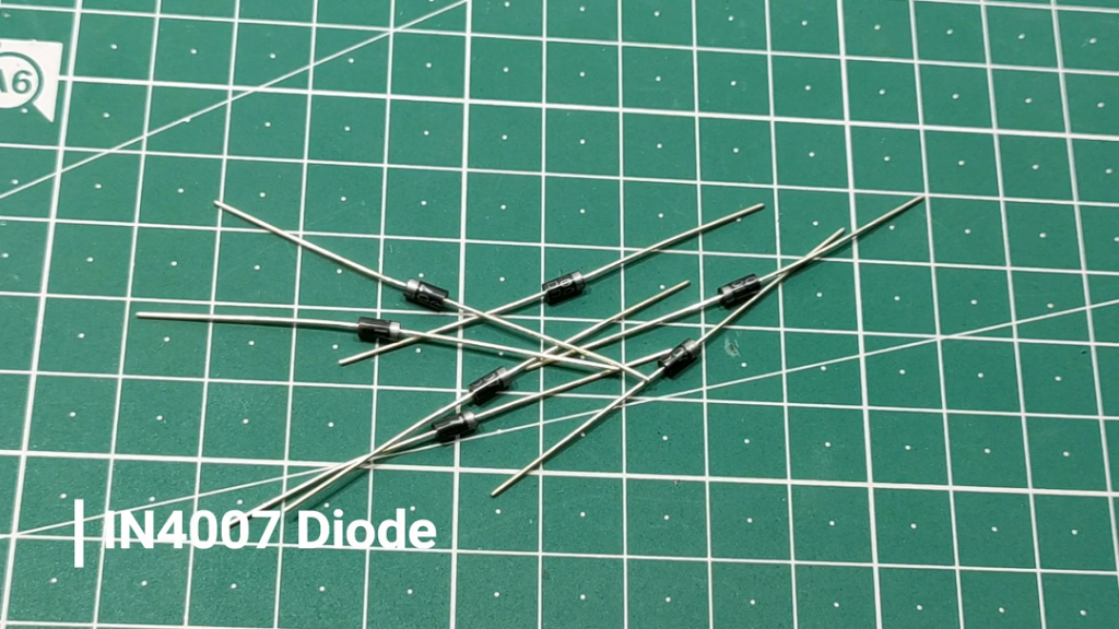
4. IN4007 Diode.
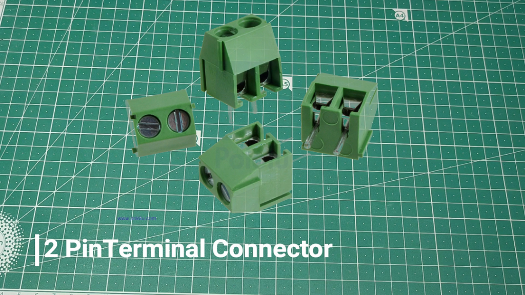
5. Two pin Terminal Connector.
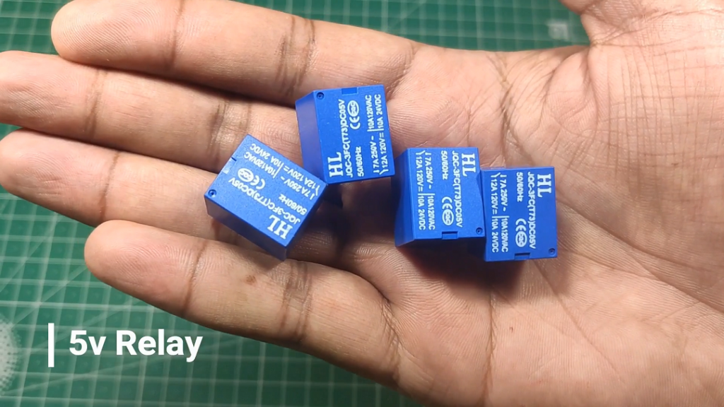
6. 5v Relay
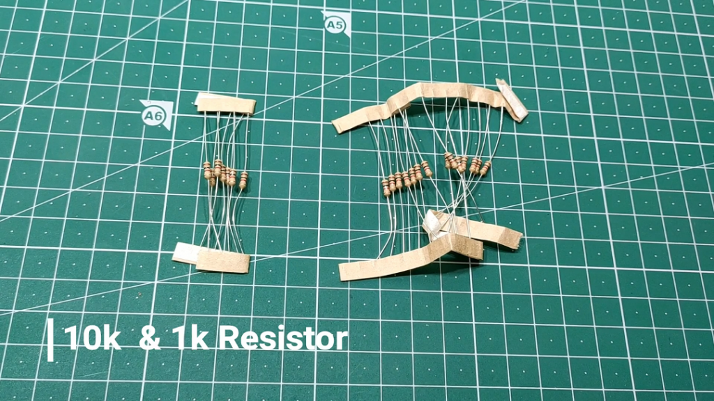
7. 1kohm & 10kohm Resistor.
8. Coustom Designed PCB.

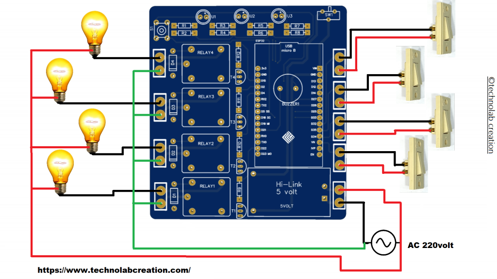
Connection of Switches and Bulb.
Connect all the switches and bulb as shown in schematics below.
Code
#ifdef ARDUINO_ARCH_ESP32
#include <WiFi.h>
#else
#include <ESP8266WiFi.h>
#endif
#include <Espalexa.h>


#define Relay1 15
#define Relay2 2
#define Relay3 4
#define Relay4 22

#define switch1 32
#define switch2 35
#define switch3 34
#define switch4 39

int switch_ON_Flag1_previous_I = 0;
int switch_ON_Flag2_previous_I = 0;
int switch_ON_Flag3_previous_I = 0;
int switch_ON_Flag4_previous_I = 0;


// prototypes
boolean connectWifi();

//callback functions
void firstLightChanged(uint8_t brightness);
void secondLightChanged(uint8_t brightness);
void thirdLightChanged(uint8_t brightness);
void fourthLightChanged(uint8_t brightness);


// Change this!!

// WiFi Credentials
const char* ssid = "xxxxxxxxxxx";
const char* password = "xxxxxxxxxxx";

// device names
String Device_1_Name = "light1";
String Device_2_Name = "light2";
String Device_3_Name = "light3";
String Device_4_Name = "light4";


boolean wifiConnected = false;

Espalexa espalexa;

void setup()
{
  Serial.begin(115200);

  pinMode(Relay1, OUTPUT);
  pinMode(Relay2, OUTPUT);
  pinMode(Relay3, OUTPUT);
  pinMode(Relay4, OUTPUT);

  pinMode(switch1, INPUT);
  pinMode(switch2, INPUT);
  pinMode(switch3, INPUT);
  pinMode(switch4, INPUT);

  digitalWrite(Relay1,LOW);
  digitalWrite(Relay2,LOW);
  digitalWrite(Relay3,LOW);
  digitalWrite(Relay4,LOW);


  // Initialise wifi connection
  wifiConnected = connectWifi();

  if (wifiConnected)
  {

    // Define your devices here.
    espalexa.addDevice(Device_1_Name, firstLightChanged); //simplest definition, default state off
    espalexa.addDevice(Device_2_Name, secondLightChanged);
    espalexa.addDevice(Device_3_Name, thirdLightChanged);
    espalexa.addDevice(Device_4_Name, fourthLightChanged);


    espalexa.begin();

  }

  else
  {
    while (1)
    {
      Serial.println("Cannot connect to WiFi. Please check data and reset the ESP.");
      delay(2500);
    }
  }

}

void loop()
{
  espalexa.loop();
  delay(1);
         //////////////////////////////////////////////////////////////////
 if (digitalRead(switch1) == LOW)
  {
    if (switch_ON_Flag1_previous_I == 0 )
    {
      digitalWrite(Relay1, LOW);
      Serial.println("Relay1- ON");

      switch_ON_Flag1_previous_I = 1;
    }


  }
  if (digitalRead(switch1) == HIGH )
  {
    if (switch_ON_Flag1_previous_I == 1)
    {
      digitalWrite(Relay1, HIGH);
      Serial.println("Relay1 OFF");

      switch_ON_Flag1_previous_I = 0;
    }

  }
 if (digitalRead(switch2) == LOW)
  {
    if (switch_ON_Flag2_previous_I == 0 )
    {
      digitalWrite(Relay2, LOW);
      Serial.println("Relay1- ON");

      switch_ON_Flag2_previous_I = 1;
    }


  }
  if (digitalRead(switch2) == HIGH )
  {
    if (switch_ON_Flag2_previous_I == 1)
    {
      digitalWrite(Relay2, HIGH);
      Serial.println("Relay1 OFF");

      switch_ON_Flag2_previous_I = 0;
    }

  }
   if (digitalRead(switch3) == LOW)
  {
    if (switch_ON_Flag3_previous_I == 0 )
    {
      digitalWrite(Relay3, LOW);
      Serial.println("Relay1- ON");

      switch_ON_Flag3_previous_I = 1;
    }


  }
  if (digitalRead(switch3) == HIGH )
  {
    if (switch_ON_Flag3_previous_I == 1)
    {
      digitalWrite(Relay3, HIGH);
      Serial.println("Relay1 OFF");

      switch_ON_Flag3_previous_I = 0;
    }

  }
 if (digitalRead(switch4) == LOW)
  {
    if (switch_ON_Flag4_previous_I == 0 )
    {
      digitalWrite(Relay4, LOW);
      Serial.println("Relay1- ON");

      switch_ON_Flag4_previous_I = 1;
    }


  }
  if (digitalRead(switch4) == HIGH )
  {
    if (switch_ON_Flag4_previous_I == 1)
    {
      digitalWrite(Relay4, HIGH);
      Serial.println("Relay1 OFF");

      switch_ON_Flag4_previous_I = 0;
    }}
}

//our callback functions
void firstLightChanged(uint8_t brightness)
{
  //Control the device
  if (brightness)
  {
    if (brightness == 255)
    {
      digitalWrite(Relay1, LOW);
      Serial.println("Device1 ON");
    }
    //Serial.print("ON, brightness ");
    //Serial.println(brightness);
  }
  else
  {
    digitalWrite(Relay1, HIGH);
    Serial.println("Device1 OFF");
  }
}


void secondLightChanged(uint8_t brightness)
{

  //Control the device
  if (brightness)
  {
    if (brightness == 255)
    {
      digitalWrite(Relay2, LOW);
      Serial.println("Device2 ON");
    }
    //Serial.print("ON, brightness ");
    //Serial.println(brightness);
  }
  else
  {
    digitalWrite(Relay2, HIGH);
    Serial.println("Device2 OFF");
  }
}

void thirdLightChanged(uint8_t brightness)
{

  //Control the device
  if (brightness)
  {
    if (brightness == 255)
    {
      digitalWrite(Relay3, LOW);
      Serial.println("Device3 ON");
    }
    //Serial.print("ON, brightness ");
    //Serial.println(brightness);
  }
  else
  {
    digitalWrite(Relay3, HIGH);
    Serial.println("Device3 OFF");
  }
}

void fourthLightChanged(uint8_t brightness)
{

  //Control the device
  if (brightness)
  {

    if (brightness == 255)
    {
      digitalWrite(Relay4, LOW);
      Serial.println("Device4 ON");
    }
    //Serial.print("ON, brightness ");
    //Serial.println(brightness);
  }
  else
  {
    digitalWrite(Relay4, HIGH);
    Serial.println("Device4 OFF");
  }
}

// connect to wifi – returns true if successful or false if not
boolean connectWifi()
{
  boolean state = true;
  int i = 0;

  WiFi.mode(WIFI_STA);
  WiFi.begin(ssid, password);
  Serial.println("");
  Serial.println("Connecting to WiFi");

  // Wait for connection
  Serial.print("Connecting...");
  while (WiFi.status() != WL_CONNECTED) {
    delay(500);
    Serial.print(".");
    if (i > 20) {
      state = false; break;
    }
    i++;
  }
  Serial.println("");
  if (state) {
    Serial.print("Connected to ");
    Serial.println(ssid);
    Serial.print("IP address: ");
    Serial.println(WiFi.localIP());
  }
  else {
    Serial.println("Connection failed.");
  }
  return state;
}
Copy the above code and upload to your esp32 board.
: A Transformative Leap into the Future")


i followed all the steps one by one exactly, but Alexa could not find any device. my esp32, alexa echo dot and alexa app of my mobile, all are under same network. still it cant discover. serial port says , esp32 is connected to my network and also shows relay status. nut no reply from alexa. can you plz help me? it will be great help for me.
Try to discover in morning time.
Dont know, but after 3-4 attempt, it Discovered the devices, and 4 channel relay board is working flawlessly. i will try to make it for 10 relays with feedback. hope for the best. Thanks for the reply, and such wonderful project. More power to you.