I have designed numerous home automation PCBs based on the ESP32 chip. To reduce costs, I did not include a programming circuit on these boards. Therefore, to flash the program into the ESP32 chip, an external programming circuit is required, or alternatively, an ESP32 development board can be used.
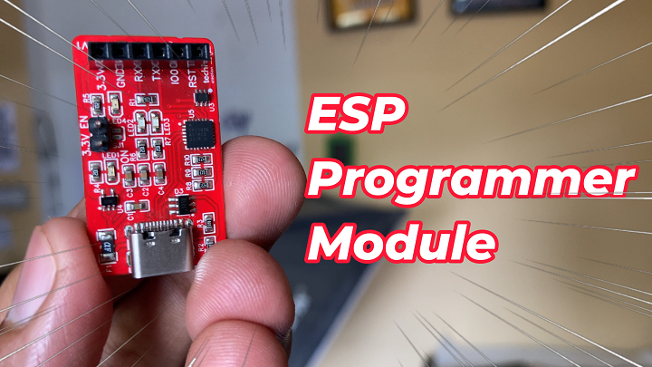
To simplify this process, I designed an ESP Programmer module. This module allows you to program any ESP chip or module effortlessly, not just the ESP32 chip.
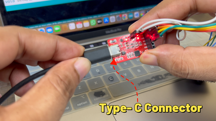
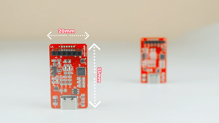
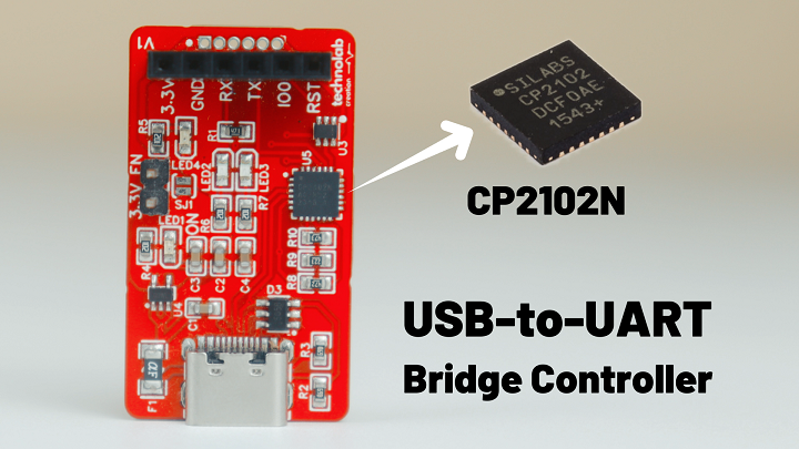
The ESP Programmer module is based on the CP2102N USB-to-UART bridge controller and features a Type-C connector. This enables direct connection to a computer for easy programming of ESP chips and modules. The module is also very compact, measuring only 20mm by 35mm.
In this article, I will explain all these details in depth. I will cover the schematic of this module, the features and specifications of the CP2102N USB-to-UART chip, and demonstrate how to flash code onto popular ESP chips and modules, including the ESP CAM Module, ESP32 chip, ESP-01 Module, and ESP8266 chip.
Features and Specifications
The CP2102N is a highly integrated USB-to-UART bridge controller, providing a simple solution for updating RS-232 designs to USB with minimal components and PCB space.
Key features and specifications of the CP2102N include:
USB 2.0 Support: Provides a 12 Mbps USB data rate.
Multiple Baud Rates: Supports baud rates from 300 bps to 3 Mbps.
Flow Control: Supports both hardware flow control (RTS/DTR) and software flow control (XON/XOFF).
EEPROM Support: Allows custom USB descriptors and power settings.
Temperature Range: Operates within a temperature range of -40°C to +85°C.
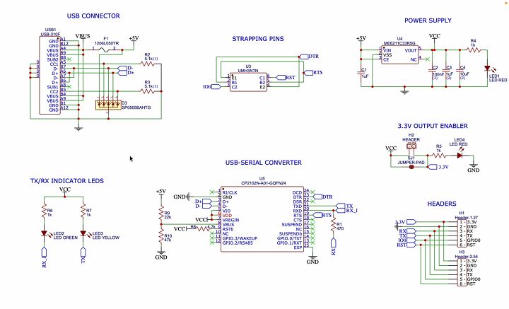
Schematic.
The ESP Programmer Schematic outlines the design of an ESP programmer using the CP2102N USB-to-UART bridge. Let’s break down the key components and their functions:
Power Supply
VCC +5V: This is the main power supply for the circuit, provided by the USB connector.
Voltage Regulator (U4 – ME6211C33R5G): Converts the +5V from the USB to a stable +3.3V needed for the ESP module.
Capacitors (C1, C2, C3, C4): These capacitors filter noise and stabilize the power supply.
USB to UART Converter (CP2102N – U5)
D- and D+: These are the USB data lines connected to the microcontroller.
VBUS: This is the USB power input.
GND: Ground connection.
TXD and RXD: These lines handle serial communication with the ESP.
DTR and RTS: Control lines used for programming the ESP.
Various GPIO Pins: General Purpose Input/Output pins for additional functionality.
Header Pins
Header-1.27 (H1) and Header-2.54 (H3): These provide connections for the ESP module.
Pins:
3.3V: Power supply for the ESP.
GND: Ground.
RX and TX: UART communication lines.
GPIO0: Used for boot mode selection during programming.
RST: Reset pin for the ESP.
Strapping Pins
Resistors (R1 to R10): These resistors are used for various strapping configurations and pull-up/pull-down settings.
Indicators
LED1, LED2, LED3, LED4: LEDs used for indicating power, data transmission, and other statuses.
USB Connector (USB1)
Standard USB connector: Provides power and data lines for communication with the computer.
Additional Components
Jumper Pad (SJ1): Configurable connection point.
Additional capacitors, resistors, and diodes: Used for signal integrity and protection.
How It All Connects
1. Power Supply:
The USB connector supplies +5V, which is regulated to +3.3V by U4.
Capacitors filter and stabilize the power supply.
2. USB to UART Communication:
The CP2102N chip handles the USB to UART conversion.
The TXD and RXD lines are used for serial communication with the ESP module.
3.Control and Programming:
The DTR and RTS lines control the programming process.
The GPIO0 and RST pins are managed to place the ESP in boot mode for programming.
4. Status Indicators:
LEDs indicate power and data activity, providing visual feedback on the programmer’s status.
This schematic allows for programming an ESP chip via a USB connection, using the CP2102N to handle the serial communication. The various headers and components ensure stable power delivery, proper signal levels, and status indication for successful programming.
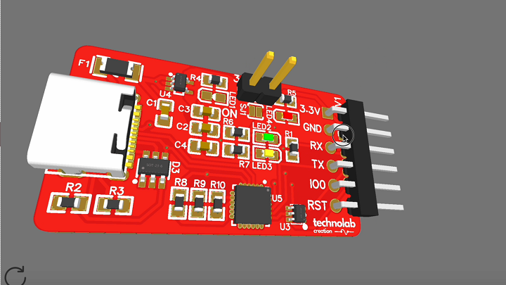
PCB Design.
After finalizing the schematic, I designed a custom PCB for it. I then placed an order with JLCPCB for PCB manufacturing.
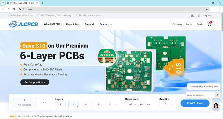
JLCPCB.
JLCPCB is a leading PCB manufacturing company in China, known for providing high-quality and reliable PCBs at very affordable prices.
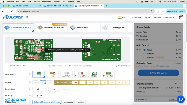
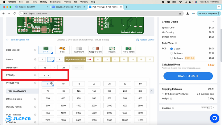
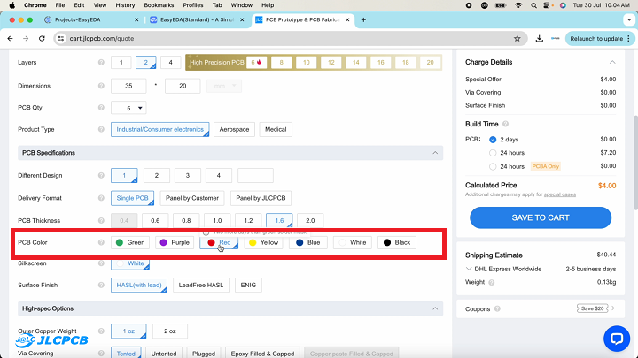
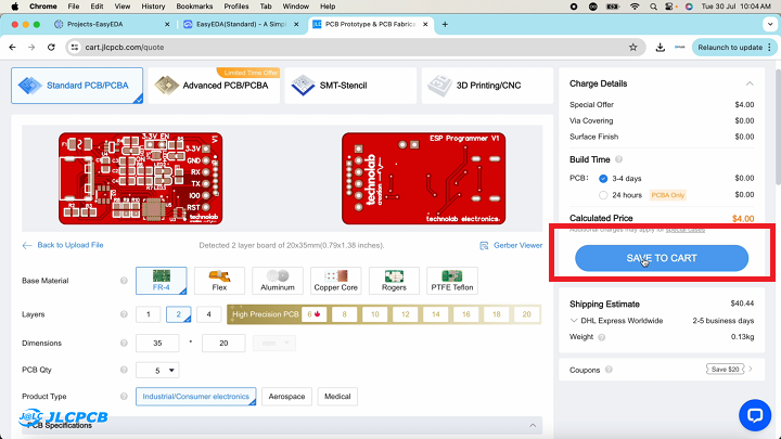
You just need to upload the Gerber file of your PCB.
select the quantity and color masking, and then click on “save to cart” to complete your order.
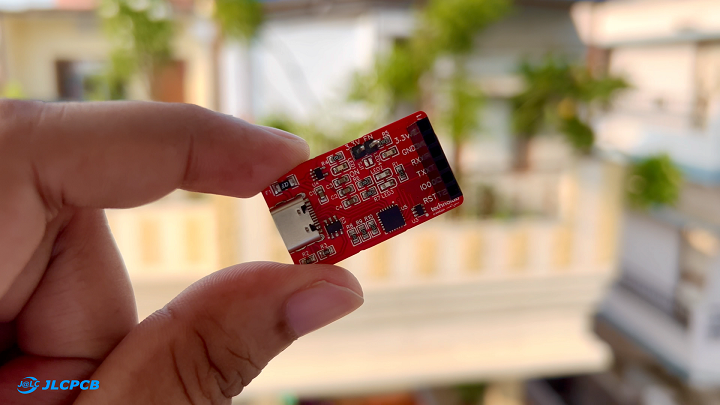
After five days, I received my PCB in very good packaging. As usual, the quality of the PCB was premium, and it looked very professional. The red color PCB looked particularly beautiful.
In addition to PCB manufacturing, JLCPCB also provides PCB assembly services, 3D printing services, and has recently started offering multicolor silkscreen PCB manufacturing services. If you have any PCB projects, I highly recommend trying out JLCPCB for your next project.
Uploading Code to ESP Boards Using the ESP Programmer Module.
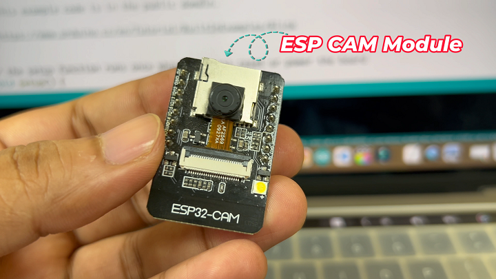
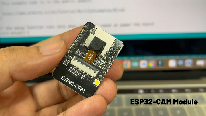
ESP32 CAM Module.
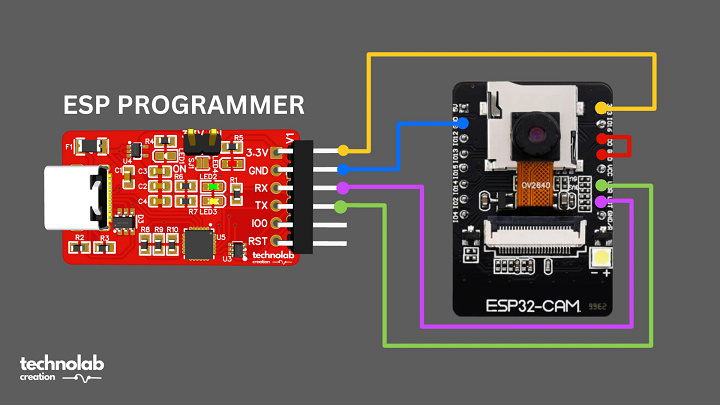
Now let’s try to upload the code to ESP boards using this ESP Programmer module. First, I will upload the code to the ESP32 CAM Module. Follow the connection diagram to connect the ESP Programmer module to the ESP32 CAM Module, and make sure to connect the GPIO 0 pin to GND (pull down the GPIO 0). Then, connect the ESP Programmer module to your computer via a Type-C cable.
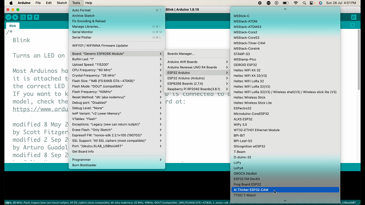
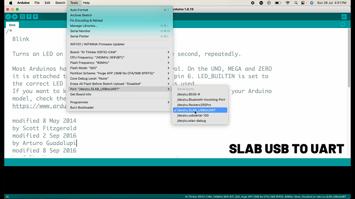
Open Arduino IDE and go to Tools > Boards. Navigate to and select the AI-thinker ESP32 CAM. Then, go to Tools again and select the right port, which will be shown as SLAB USB TO UART. If it does not show up, you need to install the CP2102N driver on your computer. The driver link for both iOS and Windows is available in the description. Just download and install it.
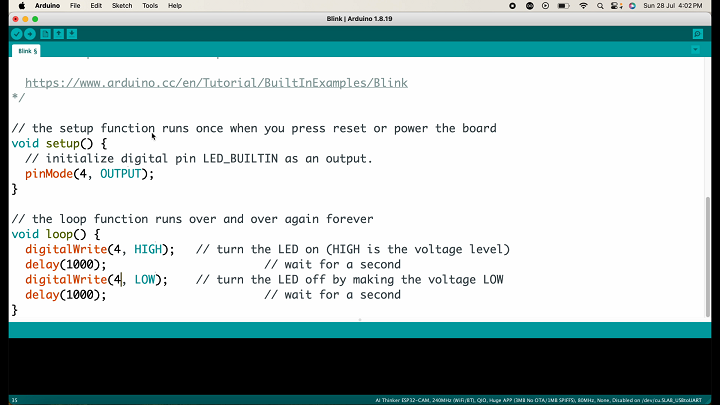
Here, I will upload a simple blink sketch in which the built-in LED will blink every second. In the ESP32 CAM Module, the built-in LED is connected to pin number 4, so change the built-in LED to GPIO 4. Now, hit the upload button.
After clicking the upload button, press the reset button on the ESP32 CAM Module. Let’s see if the code uploads correctly.
Once uploaded, remove the wires and press the reset button once. You should see the onboard LED blinking every second, indicating that our ESP Programmer module is working fine.
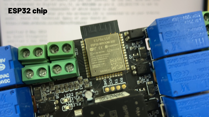
ESP32 Chip
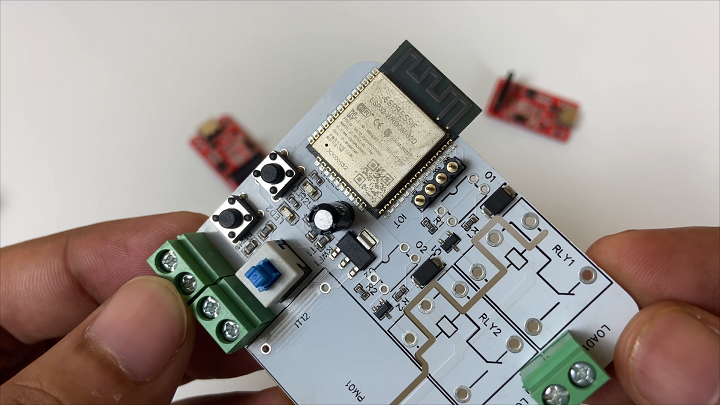
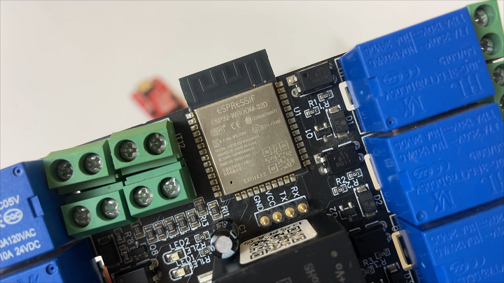
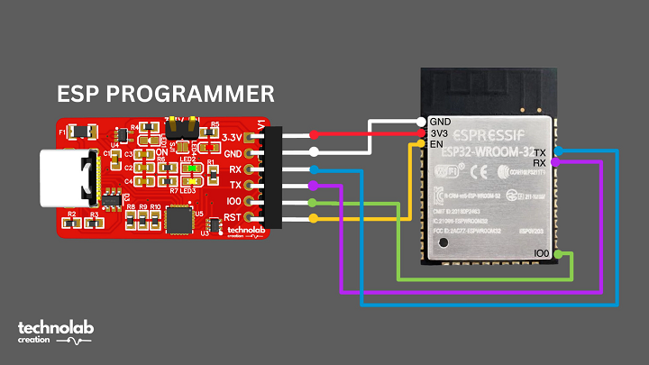
Next, let’s try to flash code to another ESP board. I will upload the code to the ESP32 chip, which is a very popular ESP chip. Although I don’t have a separate ESP32 chip, I do have a home-automation PCB with an ESP32 chip on it. Here is the connection diagram for connecting the ESP Programmer module to the ESP32 chip.
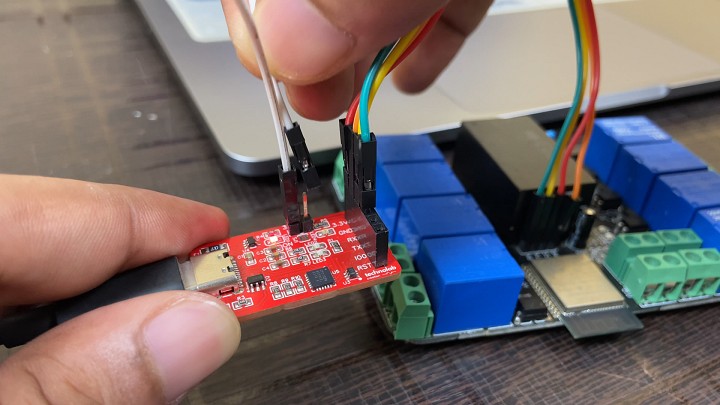
Connect your ESP32 chip to the ESP Programmer module according to this diagram. One important note: if you are using an external power supply or your ESP board is connected to another power supply, upload the code without connecting VCC wires to the ESP Programmer module. Otherwise, connect the wires to enable VCC.
Open Arduino IDE, go to Tools, and select the right board, which is the ESP32 dev board. Also, select the right communication port. I will upload the blink sketch again, but the LED is connected to pin number 12. There are actually two LEDs on the PCB, so I will modify the blink code for both LEDs. The second LED is connected to GPIO 13. Make the necessary changes in the loop section and hit the upload button.
Both LEDs are blinking, indicating that we successfully uploaded the code to the ESP32 chip using the ESP Programmer module.
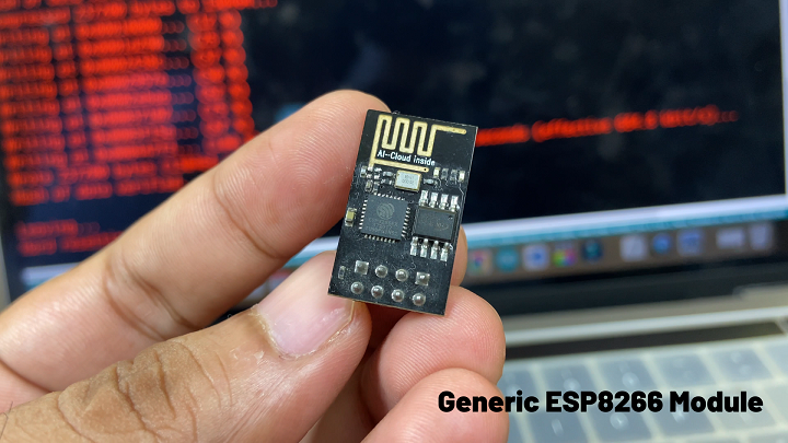
Generic ESP8266 Module
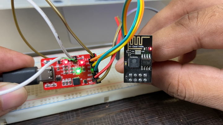
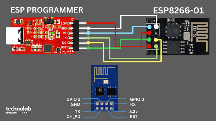
Now, I will upload the code to the generic ESP8266 module,Connect the ESP8266 Module as per the connection diagram.
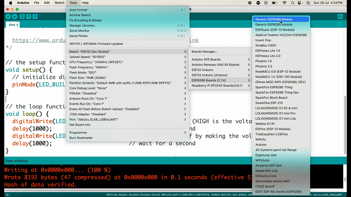
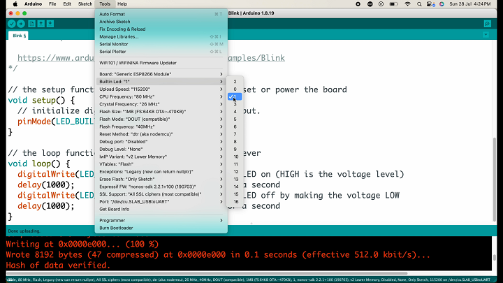
Go to Tools and select the board as the Generic ESP8266 module. Also, select the right port. In Tools, set the built-in LED to pin number 1. Click the upload button to upload the code.
The code is uploaded successfully, and the built-in LED of the ESP8266 module is blinking. This means our ESP Programmer module is working fine, and we can easily upload code to any ESP board or module.
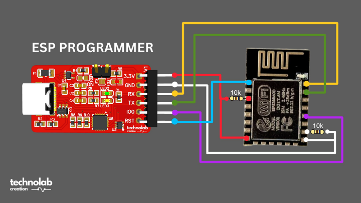
ESP12-E module
If you want to upload code to the ESP12-E module, the connection is almost the same as for the ESP32. You just need to connect two 10k resistors to pull down the GPIO 15 and EN pins. The rest is the same as for the ESP32.
That’s it for this article. I hope you learned something new.
If you want to purchase this ESP Programmer module, you can get it from my website: technolabelectronics.com.


")


