#include <WiFi.h>
#include <WiFiClient.h>
#include <BlynkSimpleEsp32.h>
BlynkTimer timer;


#define DEBUG_SW 0


#define Switch1 32
#define Relay1 19

#define Switch2 33
#define Relay2 21

#define Switch3 34
#define Relay3 22


#define Switch4 35
#define Relay4 23


#define LED1 26
#define LED2 25


int MODE = 0;


// Your WiFi credentials.
// Set password to "" for open networks.
char ssid[] = "xxxxxxxxxxxxxxxxxxxxxxxxx";
char pass[] = "xxxxxxxxxxxxx";

// You should get Auth Token in the Blynk App.
// Go to the Project Settings (nut icon).
char auth[] = "xxxxxxxxxxxxxxxxxxxxxxxxxxxxx";


int Flag1 = 0;
int Flag2 = 0;
int Flag3 = 0;
int Flag4 = 0;


BLYNK_WRITE(V1)
{
  int pinValue = param.asInt(); // assigning incoming value from pin V1 to a variable
  digitalWrite(Relay1, pinValue);
  // process received value
}

BLYNK_WRITE(V2)
{
  int pinValue = param.asInt(); // assigning incoming value from pin V2 to a variable
  digitalWrite(Relay2, pinValue);
  // process received value
}

BLYNK_WRITE(V3)
{
  int pinValue = param.asInt(); // assigning incoming value from pin V3 to a variable

  digitalWrite(Relay3, pinValue);
  // process received value
}

BLYNK_WRITE(V4)
{
  int pinValue = param.asInt(); // assigning incoming value from pin V4 to a variable
  digitalWrite(Relay4, pinValue);
  // process received value
}

void with_internet()
{
  if (digitalRead(Switch1) == LOW)
  {
    if (Flag1 == 0 )
    {
      digitalWrite(Relay1, LOW);
      if (DEBUG_SW) Serial.println("Relay1- ON");
      Blynk.virtualWrite(V1, 0);
      Flag1 = 1;
    }
    if (DEBUG_SW) Serial.println(" -ON");

  }
  if (digitalRead(Switch1) == HIGH )
  {
    if (Flag1 == 1)
    {
      digitalWrite(Relay1, HIGH);
      if (DEBUG_SW) Serial.println("Relay1 OFF");
      Blynk.virtualWrite(V1, 1);
      Flag1 = 0;
    }
    if (DEBUG_SW)Serial.println(" OFF");
  }


  if (digitalRead(Switch2) == LOW)
  {
    if (Flag2 == 0 )
    {
      digitalWrite(Relay2, LOW);
      if (DEBUG_SW)  Serial.println("Relay2- ON");
      Blynk.virtualWrite(V2, 0);
      Flag2 = 1;
    }
    if (DEBUG_SW) Serial.println("Switch2 -ON");

  }
  if (digitalRead(Switch2) == HIGH )
  {
    if (Flag2 == 1)
    {
      digitalWrite(Relay2, HIGH);
      if (DEBUG_SW) Serial.println("Relay2 OFF");
      Blynk.virtualWrite(V2, 1);
      Flag2 = 0;
    }
    if (DEBUG_SW)Serial.println("Switch2 OFF");
    //delay(200);
  }

  if (digitalRead(Switch3) == LOW)
  {
    if (Flag3 == 0 )
    {

      digitalWrite(Relay3, LOW);
      if (DEBUG_SW) Serial.println("Relay3- ON");
      Blynk.virtualWrite(V3, 0);
      Flag3 = 1;
    }
    if (DEBUG_SW) Serial.println("Switch3 -ON");

  }
  if (digitalRead(Switch3) == HIGH )
  {
    if (Flag3 == 1)
    {

      digitalWrite(Relay3, HIGH);
      if (DEBUG_SW) Serial.println("Relay3 OFF");
      Blynk.virtualWrite(V3, 1);
      Flag3 = 0;
    }
    if (DEBUG_SW)Serial.println("Switch3 OFF");
    //delay(200);
  }

  if (digitalRead(Switch4) == LOW)
  {
    if (Flag4 == 0 )
    {
      digitalWrite(Relay4, LOW);
      if (DEBUG_SW) Serial.println("Relay4- ON");
      Blynk.virtualWrite(V4, 0);
      Flag4 = 1;
    }
    if (DEBUG_SW) Serial.println("Switch4 -ON");

  }
  if (digitalRead(Switch4) == HIGH )
  {
    if (Flag4 == 1)
    {
      digitalWrite(Relay4, HIGH);
      if (DEBUG_SW) Serial.println("Relay4 OFF");
      Blynk.virtualWrite(V4, 1);
      Flag4 = 0;
    }
    if (DEBUG_SW)Serial.println("Switch4 OFF");
    //delay(200);
  }


}

void without_internet()
{

  digitalWrite(Relay1, digitalRead(Switch1));
  digitalWrite(Relay2, digitalRead(Switch2));
  digitalWrite(Relay3, digitalRead(Switch3));
  digitalWrite(Relay4, digitalRead(Switch4));

}


void checkBlynk() { // called every 3 seconds by SimpleTimer

  bool isconnected = Blynk.connected();
  if (isconnected == false) {
    MODE = 1;
    digitalWrite(LED1, HIGH);
    digitalWrite(LED2, LOW);

  }
  if (isconnected == true) {
    MODE = 0;
    digitalWrite(LED1, HIGH);
    digitalWrite(LED2, HIGH);

  }
}

void setup()
{
  // Debug console
  if (DEBUG_SW) Serial.begin(9600);
  pinMode(Switch1, INPUT);
  pinMode(Relay1, OUTPUT);

  pinMode(Switch2, INPUT);
  pinMode(Relay2, OUTPUT);

  pinMode(Switch3, INPUT);
  pinMode(Relay3, OUTPUT);

  pinMode(Switch4, INPUT);
  pinMode(Relay4, OUTPUT);


  pinMode(LED1, OUTPUT);
  pinMode(LED2, OUTPUT);


  digitalWrite(LED1, HIGH);
  delay(200);
  digitalWrite(LED2, HIGH);
  delay(200);

  digitalWrite(LED1, LOW);
  digitalWrite(LED2, LOW);

  delay(500);

  digitalWrite(LED1, HIGH);
  delay(200);
  digitalWrite(LED2, HIGH);
  delay(200);


  digitalWrite(LED1, LOW);
  digitalWrite(LED2, LOW);

  //pinMode(MODE, INPUT);
  WiFi.begin(ssid, pass);
  timer.setInterval(3000L, checkBlynk); // check if connected to Blynk server every 3 seconds
  Blynk.config(auth);//, ssid, pass);

}

void loop()
{
  if (WiFi.status() != WL_CONNECTED)
  {
    if (DEBUG_SW) Serial.println("Not Connected");
  }
  else
  {
    if (DEBUG_SW) Serial.println(" Connected");
    Blynk.run();
  }

  timer.run(); // Initiates SimpleTimer
  if (MODE == 0)
    with_internet();
  else
    without_internet();
}


: A Transformative Leap into the Future")


Hello, I’d like to make this project, but the Gerber file is no longer available? Are you able to reupload? Thank you
Check again
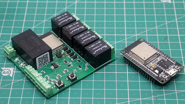
This home automation PCB with SMD components and an ESP32 chip sound like a fantastic innovation in the field of smart home technology. The use of SMT components and the ESP32 chip has enabled a significant reduction in the size of the PCB, making it more compact and efficient. The ability to control appliances through both the Blynk app and manual switches provides flexibility and convenience to users. The inclusion of onboard LEDs for Wi-Fi status is a thoughtful addition, allowing users to quickly determine the connection status. The mention of using EasyEDA for designing the PCB and PCBWay for manufacturing demonstrates a systematic approach to the project. Overall, this seems like an impressive solution for home automation enthusiasts looking for a reliable and space-saving option.