Arduino Nano Clock With Auto Brightness.

Arduino Nano Clock With Auto Brightness.

Arduino Nano Clock With Auto Brightness.

Everyone wanted a clock that shows time and date together So, In this project I’ll show you how you can build an arduino nano clock with adaptive brightness using RTC and a design PCB from PCBWay.

Arduino Nano Clock Features.

1. Shows the date and time together. switches in three seconds.

2.Adaptive brightness, i.e this clock will adjust the brightness of display according to outside light condition.

3. Easily Visible ,Due to adaptive brightness it is easily visible to day as well as in night.

4.No need to set time and date every time when power goes off. RTC takes care of correct time and date.

5.Easy to assemble, by using PCBWay pcb it is very easy to make it.

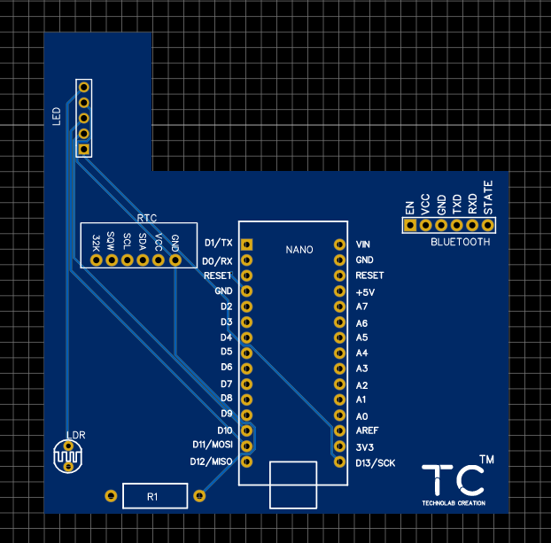
PCB for the Project.

To build this project, I’ve designed a PCB for the Arduino nano board and RTC.

I’ve designed the shield to be a compact digital clock. The PCB has a lot of features so that it can suit a lot of different projects for different applications; you can also attach bluetooth module to display data ; In fact, I didn’t use all the PCB features in this project.

The RTC module is a very interesting addition to the shield, you no need to set time and date everytime when power goes off.

Designing the PCB

To design the circuit and PCB, we used EasyEDA which is a browser based software to design PCBs.

Designing the circuit works like in any other circuit software tool, you place some components and you wire them together. Then, you assign each component to a footprint.

Having the parts assigned, place each component. When you’re happy with the layout, make all the connections and route your PCB.

Save your project and export the Gerber files.

Ordering the PCBs at PCBWay

This project is sponsored by PCBWay. PCBWay is a full feature Printed Circuit Board manufacturing service.

Turn your DIY breadboard circuits into professional PCBs – get 10 boards for approximately $5 + shipping (which will vary depending on your country).

Once you have your Gerber files, you can order the PCB. Follow the next steps.

1. Download the Gerber files – click here to download the .zip file.

2. Go to PCBWay website and open the PCB Instant Quote page. 

3. PCBWay can grab all the PCB details and automatically fills them for you. Use the “Quick-order PCB (Autofill parameters)”.

4. Press the “+ Add Gerber file” button to upload the provided Gerber files.

And that’s it. You can also use the OnlineGerberViewer to check if your PCB is looking as it should.

Now select the shipping method , the one you prefer and has cost efficient.

You can increase your PCB order quantity and change the solder mask color. I’ve ordered the Blue color.

Once you’re ready, you can order the PCBs by clicking “Save to Cart” and complete your order.

After approximately one week using the DHL shipping method, I received the PCBs at my place.

As usual, everything comes well packed, and the PCBs are really high-quality. 

The letters on the silkscreen are really well-printed and easy to read. Additionally, the solder sticks easily to the pads.

Parts Required

To assemble the circuit on a breadboard you need the following parts:

1.Arduino nano

2.RTC Module

3.LDR

4.LED matrix

5.1K Resistor

6.PCB Board from PCBWay.

7.Female Header

Schematic

After gathering all the needed parts, you can assemble the circuit by following the above schematic diagram:

Soldering the Components

The next step was soldering the components to the PCB,

Now place every components in the soldier mask of PCB board and soldire everything properly,

Use female header for the Arduino nano and RTC module so you can able to reuse these components.

The Above figure shows how the PCB looks like after soldering all the components.

Code

When your hardware is ready connect the clock to your computer to upload the code,

Download the needed code given to the link, and upload that in your arduino nano clock, after selecting the right board and port. Click here for code ...Arduino nano clock.

#include <MD_Parola.h>
#include <MD_MAX72xx.h>
#include <SPI.h>
#include <Arduino.h>
#include <RTClib.h> 


const int ldrPin = A2;
int Hr,yr,mon,d;
int Mn, sc;
byte value;
RTC_DS1307 rtc;
//#define HARDWARE_TYPE MD_MAX72XX::PAROLA_HW
#define HARDWARE_TYPE MD_MAX72XX::FC16_HW

#define MAX_DEVICES 4
#define CLK_PIN   13
#define DATA_PIN  11
#define CS_PIN    10


// Hardware SPI connection
//MD_MAX72XX mx = MD_MAX72XX(HARDWARE_TYPE, CS_PIN, MAX_DEVICES);
//MD_Parola P = MD_Parola(HARDWARE_TYPE, CS_PIN, MAX_DEVICES);
// Arbitrary output pins
MD_Parola P = MD_Parola(HARDWARE_TYPE, DATA_PIN, CLK_PIN, CS_PIN, MAX_DEVICES);

byte ledintensitySelect(int light) {
       value=round(light/250);
  return value;
};
String sign[] ={"Jan", "Feb", "Mar", "Apr", "May", "Jun","Jul", "Aug", "Sep", "Oct", "Nov", "Dec"};


void setup() 
{
  Serial.begin(9600);
  rtc.begin();
  P.begin();
  pinMode(ldrPin, INPUT);
  /////////////////////(year,month,day,hr,min,sec)
 // rtc.adjust(DateTime(2019, 11, 6, 10, 45, 30));
}


void loop()
{
  int L = analogRead(ldrPin);
  byte  L1= ledintensitySelect(L);

   DateTime now = rtc.now();
   // Save check in time;
   yr=now.year();
   mon=now.month();
   d=now.day();
   Hr = now.hour();
   Mn = now.minute();
   sc=now.second();
   String d1= String(d) + " " ;
   String s1= String(Hr) + ":" ; 
   String s2= String(Mn);
   String s3= String(sc);
   String s= s1 + s2 ;
   if (strlen(Hr)==1)
   {
    String s1="0"+ s1;
    }
   if( strlen(Mn)== 1 )
   {
    String s2 = "0"+ s2;
    }
   P.setIntensity(L1);
   P.print(s);
   delay(4000);
   P.print(d1+sign[mon-1]);
   delay(2000); 
  Serial.println(L);
  
  }

Ready to Use

Now our Clock is ready to use , you can use it anywhere

In office

In School

In home

In bedroom etc

So order your own PCB board from PCBWay and make your own digital clock.

2 thoughts on “Arduino Nano Clock With Auto Brightness.

  1. Hello,
    Great job there.
    Please, how do I add bluetooth module to display data.
    Please, respond I want to use your PCB.
    Thanks.

Leave a Reply

Your email address will not be published. Required fields are marked *

Back To Top