This article shows you, how to design and develop a programming shield for the ESP8266 WIFI module.
If you remeber my video how to program esp8266 wifi module using arduino uno board. I had mentioned that pins of esp8266 is not bread-board friendly, there I have used jumper wires and bread-board for programming esp8266 wifi module.
Apart from bread board & jumper wires, Still I had to connect level convertor resistors and push button to reset the module separetly.
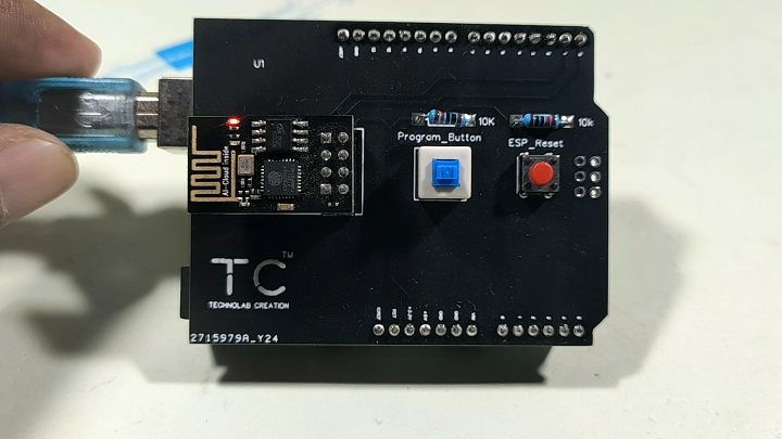
So I decided why not we make programming shield for esp8266 with all the required components like DPDT switch for selecting programming mode and normal mode.
Push button is used for reset , headers to insert the esp8266 wifi module into arduino uno board.
And level is convertor resistors are for the RX pin of esp8266 module.
Designing the PCB.
To design the circuit and PCB, we used EasyEDA which is a browser based software to design PCBs.
Designing the circuit works like in any other circuit software tool, you place some components and you wire them together.
Then, you assign each component to a footprint.
Having the parts assigned, place each component. When you’re happy with the layout, make all the connections and route your PCB.
Save your project and export the Gerber files.
Ordering the PCBs at PCBWay
This project is sponsored by PCBWay. PCBWay is a full feature Printed Circuit Board manufacturing service.
Turn your DIY breadboard circuits into professional PCBs – get 10 boards for approximately $5 + shipping (which will vary depending on your country).
Once you have your Gerber files, you can order the PCB. Follow the next steps.
Now grab all the components whose list is mention above, and soldered on the PCB.
After assembling the all the components on the pcb, press the switch button to make the module go inside the programming mode and press the reset button once.
Now esp8266 is in programming mode.
Getting arduino IDE ready.
Esp8266 wifi module can be programmed using arduino ide and in order to do that , we need to make few changes in the arduino ide rather we have to add esp8266 boards in arduino ide.
Follow the below instruction to make the changes.
1. Go to file in the arduino ide and then in the preferences.


: A Transformative Leap into the Future")