

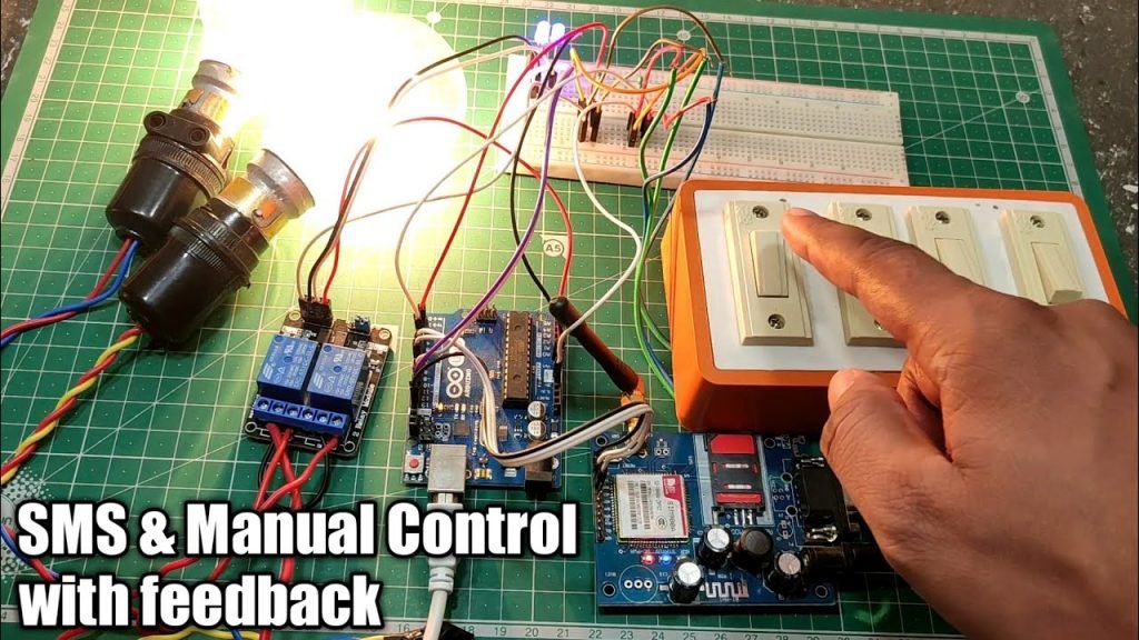
Welcome to another POST, Now in this Tutorial we are going to build a project in which we control our home appliances by sending a text sms from our phone and not only by a text sms we also able to control manually by our regular switches as we always do.
And apart from this we can also check the status of our home appliances either it is ON or OFF,….. just BY sending a text sms.,for example ….if we wanted to check that relay one is on or off …..we have to just send a text sms i.e. RELAY1STATE.
and we will get revert text sms with real time status.
This is very intersting and usefull project for homeautomation in those remote locations where internet and wifi is not available.
Components Requried
1. Arduino Uno
2. Gsm Module SIM900A
3.Relay Module
4.Bread Board
5.Jumper Wires
6. 10kohm Resistance X2
7. Switch Button
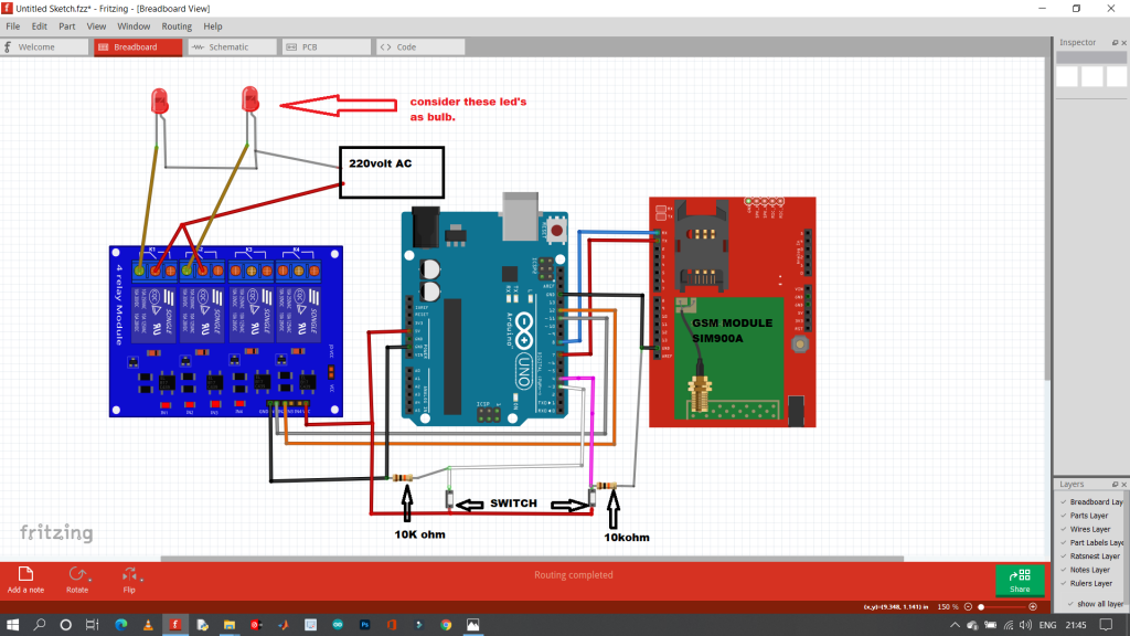
Circuit Diagram
CODE
// Include Software Serial library to communicate with GSM
#include <SoftwareSerial.h>
//#define DEBUG_SW 0
// Configure software serial port
SoftwareSerial SIM900(7, 8);
// Variable to store text message
String textMessage;
// Create a variable to store Lamp state
String Relay1State = "HIGH";
String Relay2State = "HIGH";
const int relay1 = 11; // relay1 connected to pin 12
const int relay2 = 12; // relay2 connected to pin 11
#define switch1 4 // switch1 connected to pin 4
#define switch2 3 // switch1 connected to pin 5
int switch_ON_Flag1_previous_I = 0;
int switch_ON_Flag2_previous_I = 0;
void setup() {
// Automatically turn on the shield
digitalWrite(9, HIGH);
delay(1000);
digitalWrite(9, LOW);
delay(5000);
// Set both realy as OUTPUT
pinMode(relay1, OUTPUT);
pinMode(relay2, OUTPUT);
pinMode(switch1, INPUT);
pinMode(switch2, INPUT);
// By default both the relay is off
digitalWrite(relay1, HIGH);
digitalWrite(relay2, HIGH);
// Initializing serial commmunication
Serial.begin(19200);
SIM900.begin(19200);
// Give time to your GSM shield log on to network
delay(20000);
Serial.print("SIM900 ready...");
// AT command to set SIM900 to SMS mode
SIM900.print("AT+CMGF=1\r");
delay(100);
// Set module to send SMS data to serial out upon receipt
SIM900.print("AT+CNMI=2,2,0,0,0\r");
delay(100);
}
void loop(){
if(SIM900.available()>0){
textMessage = SIM900.readString();
Serial.print(textMessage);
textMessage.toUpperCase();
delay(10);
}
if(textMessage.indexOf("RELAY1ON")>=0){
// Turn on relay1 and save current state
digitalWrite(relay1, HIGH);
Relay1State = "on";
Serial.println("Relay1 set to ON");
textMessage = "";
}
if(textMessage.indexOf("RELAY1OFF")>=0){
// Turn off relay1 and save current state
digitalWrite(relay1, LOW);
Relay1State = "off";
Serial.println("relay1 set to OFF");
textMessage = "";
}
//////////////////////////////////////////////////////
if(textMessage.indexOf("RELAY2ON")>=0){
// Turn on relay2 and save current state
digitalWrite(relay2, HIGH);
Relay2State = "on";
Serial.println("Relay2 set to ON");
textMessage = "";
}
if(textMessage.indexOf("RELAY2OFF")>=0){
// Turn off relay2 and save current state
digitalWrite(relay2, LOW);
Relay2State = "off";
Serial.println("relay2 set to OFF");
textMessage = "";
}
//////////////////////////////////////////////////////
if (digitalRead(switch1) == LOW)
{
if (switch_ON_Flag1_previous_I == 0 )
{
digitalWrite(relay1, LOW);
Relay1State = "off";
Serial.println("relay1 set to OFF");
switch_ON_Flag1_previous_I = 1;
}
}
if (digitalRead(switch1) == HIGH)
{
if (switch_ON_Flag1_previous_I == 1)
{
digitalWrite(relay1, HIGH);
Relay1State = "on";
Serial.println("Relay1 set to ON");
switch_ON_Flag1_previous_I = 0;
}
}
if (digitalRead(switch2) == LOW)
{
if (switch_ON_Flag2_previous_I == 0 )
{
digitalWrite(relay2, LOW);
Relay2State = "off";
Serial.println("relay2 set to OFF");
switch_ON_Flag2_previous_I = 1;
}
}
if (digitalRead(switch2) == HIGH)
{
if (switch_ON_Flag2_previous_I == 1)
{
digitalWrite(relay2, HIGH);
Relay2State = "on";
Serial.println("Relay2 set to ON");
switch_ON_Flag2_previous_I = 0;
}
}
/////////////////////////////////////////////////////
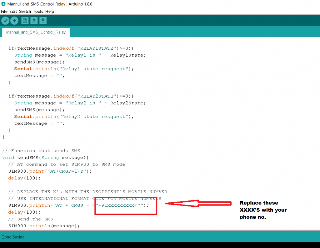
if(textMessage.indexOf("RELAY1STATE")>=0){
String message = "Relay1 is " + Relay1State;
sendSMS(message);
Serial.println("Relay1 state resquest");
textMessage = "";
}
if(textMessage.indexOf("RELAY2STATE")>=0){
String message = "Relay2 is " + Relay2State;
sendSMS(message);
Serial.println("Relay2 state resquest");
textMessage = "";
}
}
// Function that sends SMS
void sendSMS(String message){
// AT command to set SIM900 to SMS mode
SIM900.print("AT+CMGF=1\r");
delay(100);
// REPLACE THE X's WITH THE RECIPIENT'S MOBILE NUMBER
// USE INTERNATIONAL FORMAT CODE FOR MOBILE NUMBERS
SIM900.println("AT + CMGS = \"+91XXXXXXXXX\"");
delay(100);
// Send the SMS
SIM900.println(message);
delay(100);
// End AT command with a ^Z, ASCII code 26
SIM900.println((char)26);
delay(100);
SIM900.println();
// Give module time to send SMS
delay(5000);
}


Please what’s d essence of those 10k ohms resistors and why 10k, why no 5 or lesser
10kohm resistor is used as pulldown resistors you could use here 5k instead of 10k it will work perfectly.
What is mean by pulldown?
A pull-down resistor connects unused input pins (OR and NOR gates) to ground, (0V) to keep the given input LOW. The resistance value for a pull-up resistor is not usually that critical but must maintain the input pin voltage above VIH.
Can we use any type of resistor or 10k,5k is must?
I have just 220ohm resistor.
Use 10k resistor.
It is with sad regret we are shutting down.
We have made all our leads available for a one time fee on DataList2023.com
Regards,
Rusty