In this article we will learn about LoRa and also make a small home-Automation system using a Reyax LoRa RYLR998 Module.
Here LoRa stands for Long Range, LoRa is a wireless transmission protocol, and consume very low power and has very long range of transmission distance, we can transmit data near about 10km , Unlike WIFI and blue-tooth which has range of only few meters.
LoRa transmission range depends upon which type of LoRa module we are using, some module has range 100’s of kilometer.
LoRa modules are very small in size and available in a very cheap price, so we can use these LoRa modules in place of WIFI and blue-tooth modules , which are very expensive.
LoRa modules are very useful in remote locations where internet connection is not available.
In this article, I am going to use RYLR998 LoRa module from Reyax , which can be easily control by AT Commands. and also I will make a small home-automation system by using this module with Arduino Uno & Nano Boards.
Configuring LoRa Module.
To use these modules in projects first we need to set frequency band, Network ID and address of transmitter and receiver, for that we have to connect these LoRa modules with our computer via USB to serial interface.
Now connect FTDI232 Interface module with LoRa module as per schematic shown below.
VDD TO VCC.
GND TO GND.
RX PIN OF LORA TO TX OF PIN OF FTDI232 MODULE.
TX PIN OF LORA TO RX PIN OF FTDI232 MODULE.
And one most important thing, On the FTDI232 module you have to select logic level 3.3.
After making the connection now connect the USB to serial interface module with your computer to set the parameters.
This is the LoRa AT command guide for Reyax LoRa module.
Now open Arduino ide, and then open tools, there you have to select the right com port. After selecting port open serial monitor.
You have to select the baud rate 115200 which is default baud rate of LoRa modules
and select both NL and CR.
let test it, Type AT and hit enter, If you get +OK response from module that’s means LoRa module is now communicating with our computer.
Now lets configure the parameters of the LoRa module, By using AT command.
Type AT+ADDRESS=1 , this address 1 is for the transmitter and for the receiver it will be 2,
You could give any address you want, Address could be in between 0 to 65000.
Type AT+NETWORKID=5 again you can give any number in between 3 to 15.
And this Network ID will be same for both transmitter as well as for receiver.
And in similar manner we have to configure the frequency band of this LoRa modules
and one most important thing there are some allowable frequency band which you can only use in wireless transmitter, to know the eligible band in your country just search on google , In my case it is Approx 865Mhz.
Type AT+BAND=865000000 and here we got ‘Ok’ that’s means band is successfully setup.
Schematics.
Transmitter Circuit.
Make the transmitter part of circuit as per the schematic shown below.
Receiver Circuit.
Make receiver part of circuit as per diagram shown below.
If you don’t have this PCB, Still you can make this project, just follow the below schematics.
Designing the PCB.
To design the circuit and PCB, we used EasyEDA which is a browser based software to design PCBs.
Designing the circuit works like in any other circuit software tool, you place some components and you wire them together.
Then, you assign each component to a footprint.
Having the parts assigned, place each component. When you’re happy with the layout, make all the connections and route your PCB.
Ordering the PCBs at PCBWay.
This project is sponsored by PCBWay. PCBWay is a full feature Printed Circuit Board manufacturing service.
Turn your DIY breadboard circuits into professional PCBs – get 10 boards for approximately $5 + shipping (which will vary depending on your country).
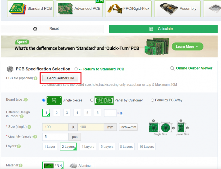
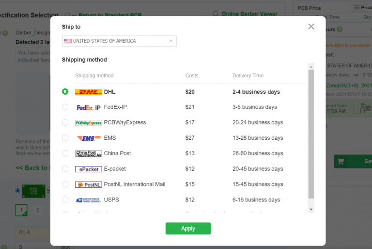
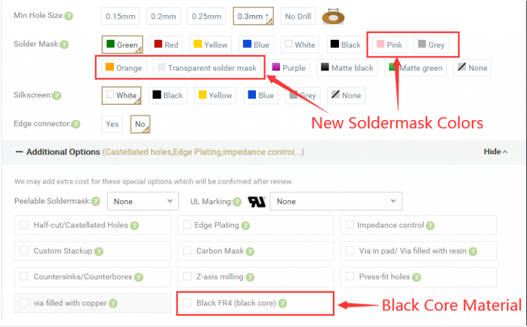
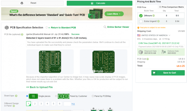
Once you have your Gerber files, you can order the PCB. Follow the next steps.
3 thoughts on “Reyax RYLR998 LoRa Module with Arduino.”
What is logic level output voltage of ESP32 (ESP32 ESP-WROOM-32 )? 5v or 3.3v?
I have to connect Lora module “REYAX RYLR998” to it, which works with 3.3v only.
I lost whole day but could not succeed in sending AT command using SoftwareSerial, I have ESP32 Dev Unit
SoftwareSerial lora(16, 17);
const int NETWORKID_LORA=5; //enter Lora Network ID
const int ADDRESS_LORA_NODE_GATEWAY=1;
lora.begin(115200); // default baud rate of module is 115200
delay(1000); // wait for LoRa module to be ready
lora.print((String)”AT+ADDRESS=” + ADDRESS_LORA_NODE_GATEWAY + “\r\n”);
delay(200);
lora.print((String)”AT+NETWORKID=” + NETWORKID_LORA + “\r\n”);
delay(200);
Please help


What is logic level output voltage of ESP32 (ESP32 ESP-WROOM-32 )? 5v or 3.3v?
I have to connect Lora module “REYAX RYLR998” to it, which works with 3.3v only.
logic level of ESP32 is 3.3volt and yes you can connect ESP32 directly with REYAX RYLR998.
I lost whole day but could not succeed in sending AT command using SoftwareSerial, I have ESP32 Dev Unit
SoftwareSerial lora(16, 17);
const int NETWORKID_LORA=5; //enter Lora Network ID
const int ADDRESS_LORA_NODE_GATEWAY=1;
lora.begin(115200); // default baud rate of module is 115200
delay(1000); // wait for LoRa module to be ready
lora.print((String)”AT+ADDRESS=” + ADDRESS_LORA_NODE_GATEWAY + “\r\n”);
delay(200);
lora.print((String)”AT+NETWORKID=” + NETWORKID_LORA + “\r\n”);
delay(200);
Please help