Now-days almost everyone has smart speakers in their house like Amazon Alexa or google assistant. I have Amazon Alexa in my house, the quality of voice assistant is amazing. You can ask anything to Alexa and Alexa will give response in no-time. Talking to Alexa is always a fun. Apart from this we can also use Alexa to automate our home appliances. That means we can control our home-appliances just giving voice command to Alexa.
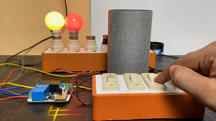
In this IoT project, I have shown how to make an IoT-based ESP32 Alexa Smart Home System to control 2 home appliances from the manual switch & Amazon Alexa App. If the internet is not available, then you can control the home appliances from manual switches. During the article, I have shown all the steps to make this home automation system.
This ESP32 control smart relay has the following features:
Control home appliances with voice commands using Alexa
Control home appliances with manual switches.
Monitor real-time feedback in the Alexa App.
Control home appliances manually without internet.
Just need Echo Dot. No third-party app required.
Designing the PCB.
To design the circuit and PCB, we used EasyEDA which is a browser based software to design PCBs.
Designing the circuit works like in any other circuit software tool, you place some components and you wire them together. Then, you assign each component to a footprint.
Having the parts assigned, place each component. When you’re happy with the layout, make all the connections and route your PCB.
Save your project and export the Gerber files.
Ordering the PCBs at PCBWay.
This project is sponsored by PCBWay. PCBWay is a full feature Printed Circuit Board manufacturing service.
Turn your DIY breadboard circuits into professional PCBs – get 10 boards for approximately $5 + shipping (which will vary depending on your country).
Once you have your Gerber files, you can order the PCB. Follow the next steps.
#include <WiFi.h>
#include <Espalexa.h>
#include <AceButton.h>
using namespace ace_button;

Espalexa espalexa;

// define the GPIO connected with Relays and switches
#define RelayPin1 23
#define RelayPin2 22


#define SwitchPin1 32
#define SwitchPin2 33


#define wifiLed    12
#define Led    13

// WiFi Credentials
const char* ssid = "technolab fibre";
const char* password = "@technolab4";

// device names
String Device_1_Name = "Light one";
String Device_2_Name = "Light two";


// prototypes
boolean connectWifi();

//callback functions
void firstLightChanged(uint8_t brightness);
void secondLightChanged(uint8_t brightness);


ButtonConfig config1;
AceButton button1(&config1);
ButtonConfig config2;
AceButton button2(&config2);


void handleEvent1(AceButton*, uint8_t, uint8_t);
void handleEvent2(AceButton*, uint8_t, uint8_t);


boolean wifiConnected = false;

//our callback functions
void firstLightChanged(uint8_t brightness)
{
  //Control the device
  if (brightness == 255)
    {
      digitalWrite(RelayPin1, HIGH);
      Serial.println("Device1 ON");
    }
  else
  {
    digitalWrite(RelayPin1, LOW);
    Serial.println("Device1 OFF");
  }
}

void secondLightChanged(uint8_t brightness)
{
  //Control the device
  if (brightness == 255)
    {
      digitalWrite(RelayPin2, HIGH);
      Serial.println("Device2 ON");
    }
  else
  {
    digitalWrite(RelayPin2, LOW);
    Serial.println("Device2 OFF");
  }
}

// connect to wifi – returns true if successful or false if not
boolean connectWifi()
{
  boolean state = true;
  int i = 0;

  WiFi.mode(WIFI_STA);
  WiFi.begin(ssid, password);
  Serial.println("");
  Serial.println("Connecting to WiFi");

  // Wait for connection
  Serial.print("Connecting...");
  while (WiFi.status() != WL_CONNECTED) {
    delay(500);
    Serial.print(".");
    if (i > 20) {
      state = false; break;
    }
    i++;
  }
  Serial.println("");
  if (state) {
    Serial.print("Connected to ");
    Serial.println(ssid);
    Serial.print("IP address: ");
    Serial.println(WiFi.localIP());
  }
  else {
    Serial.println("Connection failed.");
  }
  return state;
}

void addDevices(){
  // Define your devices here.
  espalexa.addDevice(Device_1_Name, firstLightChanged); //simplest definition, default state off
  espalexa.addDevice(Device_2_Name, secondLightChanged);


  espalexa.begin();
}

void setup()
{
  Serial.begin(115200);

  pinMode(RelayPin1, OUTPUT);
  pinMode(RelayPin2, OUTPUT);


  pinMode(wifiLed, OUTPUT);
  pinMode(Led, OUTPUT);

  pinMode(SwitchPin1, INPUT);
  pinMode(SwitchPin2, INPUT);


  //During Starting all Relays should TURN OFF
  digitalWrite(RelayPin1, HIGH);
  digitalWrite(RelayPin2, HIGH);


  config1.setEventHandler(button1Handler);
  config2.setEventHandler(button2Handler);


  button1.init(SwitchPin1);
  button2.init(SwitchPin2);

  digitalWrite(Led, HIGH);


  // Initialise wifi connection
  wifiConnected = connectWifi();

  if (wifiConnected)
  {
    addDevices();
  }
  else
  {
    Serial.println("Cannot connect to WiFi. So in Manual Mode");
    delay(1000);
  }
}

void loop()
{
   if (WiFi.status() != WL_CONNECTED)
  {
    //Serial.print("WiFi Not Connected ");
    digitalWrite(wifiLed, LOW); //Turn off WiFi LED
  }
  else
  {
    //Serial.print("WiFi Connected  ");
    digitalWrite(wifiLed, HIGH);
    //Manual Switch Control
    //WiFi Control
    if (wifiConnected){
      espalexa.loop();
      delay(1);
    }
    else {
      wifiConnected = connectWifi(); // Initialise wifi connection
      if(wifiConnected){
      addDevices();
      }
    }
  }
  button1.check();
  button2.check();


}

void button1Handler(AceButton* button, uint8_t eventType, uint8_t buttonState) {
  Serial.println("EVENT1");
  EspalexaDevice* d1 = espalexa.getDevice(0); //this will get "first device", the index is zero-based
  switch (eventType) {
    case AceButton::kEventPressed:
      Serial.println("kEventPressed");
      d1->setPercent(100); //set value "brightness" in percent
      digitalWrite(RelayPin1, LOW);
      break;
    case AceButton::kEventReleased:
      Serial.println("kEventReleased");
      d1->setPercent(0); //set value "brightness" in percent
      digitalWrite(RelayPin1, HIGH);
      break;
  }
}

void button2Handler(AceButton* button, uint8_t eventType, uint8_t buttonState) {
  Serial.println("EVENT2");
  EspalexaDevice* d2 = espalexa.getDevice(1);
  switch (eventType) {
    case AceButton::kEventPressed:
      Serial.println("kEventPressed");
      d2->setPercent(100);
      digitalWrite(RelayPin2, LOW);
      break;
    case AceButton::kEventReleased:
      Serial.println("kEventReleased");
      d2->setPercent(0);
      digitalWrite(RelayPin2, HIGH);
      break;
  }
}
Before you upload the code you need to make some changes in the code., first of all you need to add the esp32 boards in your Arduino IDE.
And also you need to add ESP-Alexa and ace button Library in your Arduino IDE to run this code.
For this go to tools then manage libraries, a popup will come, In the search box type espalexa.
Install the first library that has come, after selecting latest version of it.
In same way install the acebutton library.
In this section of code you have to enter the SSID and Password of your router or hotspot.
And here we define the two devices, also we give the name of both devices.
These names will appear in the Alexa App when we will connect esp32 with Alexa.
More truly these are the names of devices. You can give any name you want according to your choice.
After that code will remain same no need to change anything just download this code from the video description and make the changes that I just told and straight forward upload this code after selecting right board and COM port.
While uploading the code press and hold the boot button and press the reset button once to make this module go inside boot Mode.
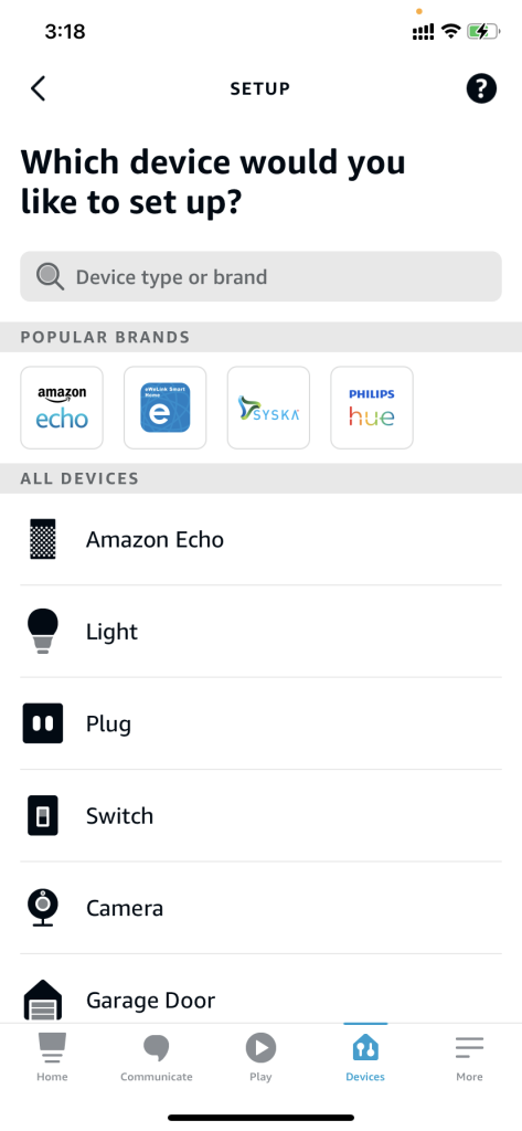
Amazon Alexa App Configuration.
Download Amazon Alexa app in your smartphone, this app is available for both iOS as well as for Android.
In the app tap on devices.
then tap on plus icon on the right top corner of the app, then add devices.
Scroll down and select other…
Click on discover devices.
Alexa speaker will search for the devices….it will take few seconds to find the devices.
Connection of bulb & switches.
Make all the connection of bulb and switches as per the schematic shown below.
After making the connections of bulb & switches , our home-automation system is ready to use. I have install this system in my house and it works like charm.
Let me know in the comment section, where you have install this system and also you can ask me any question regarding this home-automation system.
If you face any problem feel free to comment below , I will surly help you out.
Thank you so much for reading, stay healthy & safe.