Hello friends, welcome to another article. In this tutorial we will learn about AC dimmer circuit and will make one using TRIAC.
If we want to turn ON/OFF our home-appliances like TV, BULB, FAN etc. we can directly do this digitally using Relay with any microcontroller like Arduino. Here turning ON/OFF is great way of making home-automation setup. but in some cases we don’t need only digitally ON/OFF we also want, like controlling the speed of fan, brightness of bulb. these mechanism we can not achieve using relay. Here we need AC dimmer circuit to control the brightness of bulb or speed of fan.
In DC circuit we achieve this mechanism using PWM pins of microcontroller we don’t need separate circuit for it.
There are lots of ways to make AC dimmer circuit, In this article we will use phase control technique and static switches like TRIAC to control the phase of AC supply voltage.
Here a TRIAC is used to switch the AC lamp, as this is a Power electronic fast switching device which is the best suited for these applications.
Components Required.
BT136 TRIAC.
MOC3021 IC.
MCT2e IC.
Bridge Rectifier.
47k 1W Resistor.
330e Resistor.
1k Resistor.
10k Resistor.
2 pin Terminal Connector.
ESP32(as a microcontroller)
Zero crossing detector.
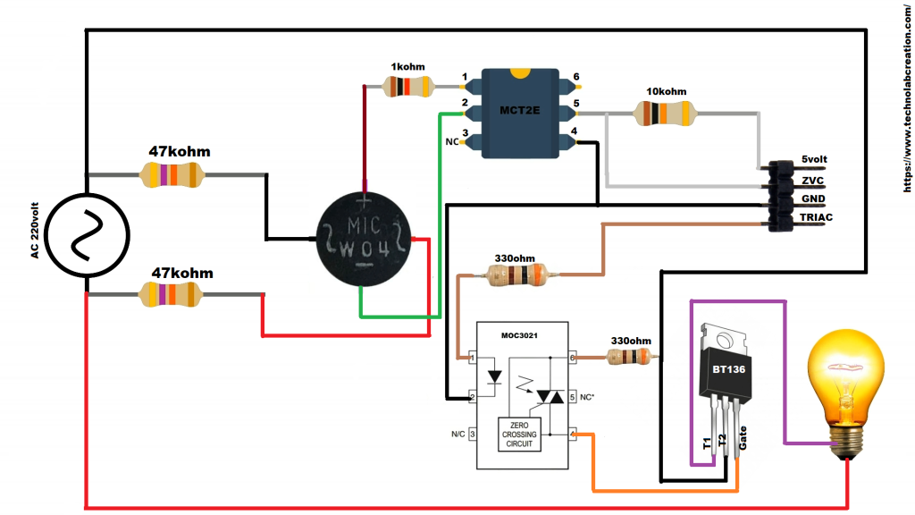
To control the AC voltage, the first thing we have to do is, to detect the zero crossing of the AC signal. In my country( India), the frequency of AC signal is 50 Hz and as it is alternating in nature. Hence, every time the signal comes to Zero point, we have to detect that point and after that trigger the TRIAC as per the power requirement. In the circuit we have one zero cross detector which gives signal to the ESP32 board whenever the signal crosses the zero value. Zero cross detector is used as a reference to change the phase of the signal. By delivering the power for less then 100% , we cut down the amount of power delivered to the appliances. The Zero crossing point of an AC signal is shown below:
Grab all the components whose list is mention above and make connections as per above diagram.
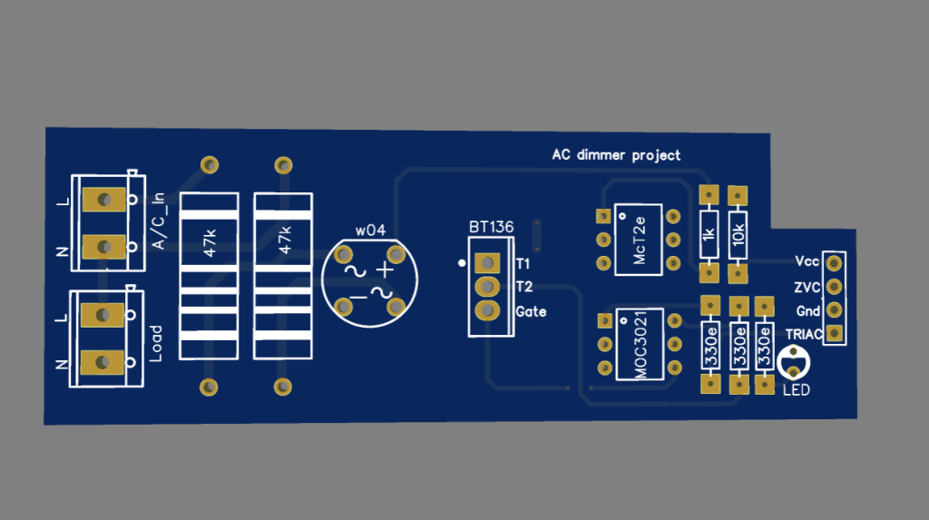
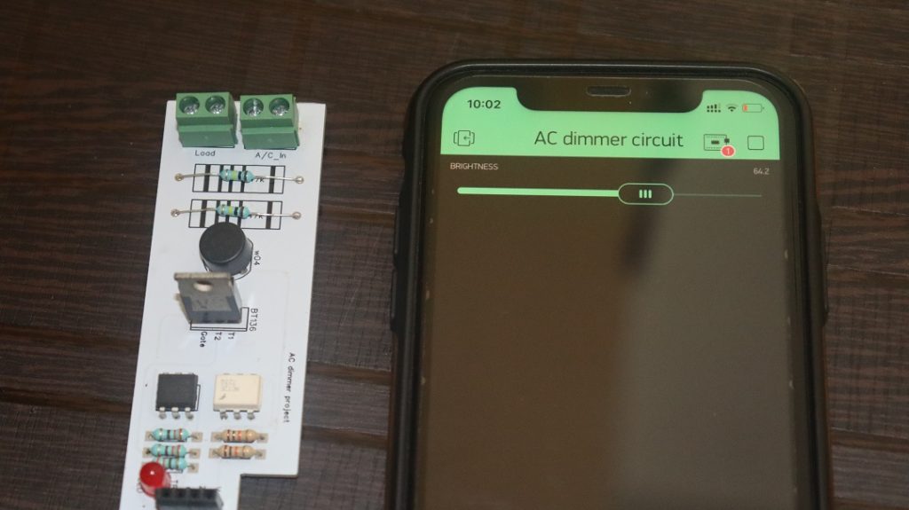
AC Dimmer PCB.
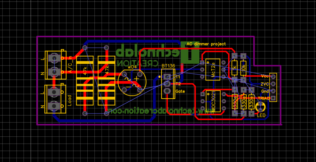
To avoid the loos wiring and to make the circuit compact , I have design PCB for AC dimmer circuit.
Designing the PCB.
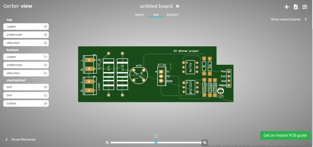
To design the circuit and PCB, we used EasyEDA which is a browser based software to design PCBs.
Designing the circuit works like in any other circuit software tool, you place some components and you wire them together. Then, you assign each component to a footprint.
Having the parts assigned, place each component. When you’re happy with the layout, make all the connections and route your PCB.
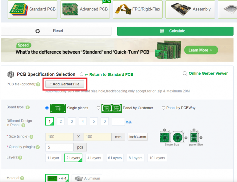
Save your project and export the Gerber files
Ordering the PCBs at PCBWay.
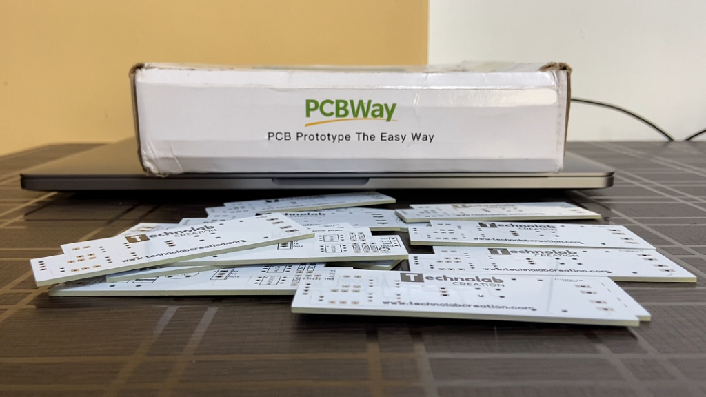
This project is sponsored by PCBWay. PCBWay is a full feature Printed Circuit Board manufacturing service.
Turn your DIY breadboard circuits into professional PCBs – get 10 boards for approximately $5 + shipping (which will vary depending on your country).
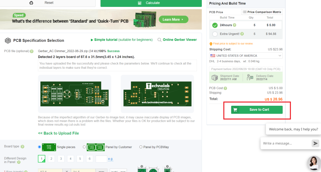
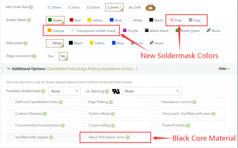
Once you have your Gerber files, you can order the PCB. Follow the next steps.
#define BLYNK_PRINT Serial
#include <WiFi.h>
#include <BlynkSimpleEsp32.h>

#define triacPulse 14
#define ZVC 27

int Slider_Value;
int dimming;
int x = 0;

char auth[] = "h1em74_mWcISOBbrENl_3BKoWGuZzWDp";        // You should get Auth Token in the Blynk App.
// Go to the Project Settings (nut icon) in the Blynk app or check your email for auth token.

char ssid[] = "technolab fibre";         // Your WiFi credentials.
char pass[] = "@technolab4";    // Set password to "" for open networks.


BLYNK_WRITE(V1)   // function to assign value to variable Slider_Value whenever slider changes position
{
  Slider_Value = param.asInt(); // assigning incoming value from pin V1 to a variable
}


void setup()
{

  pinMode(ZVC, INPUT_PULLUP);
  //digitalWrite(2, INPUT_PULLUP); // pull up
  pinMode(triacPulse, OUTPUT);
  Serial.begin(9600);
  Blynk.begin(auth, ssid, pass);
  attachInterrupt(digitalPinToInterrupt(ZVC), acon, FALLING); // attach Interrupt at PIN2
}


void loop()
{
  Blynk.run();
  // When the switch is closed
  dimming = map(Slider_Value, 0, 100, 7200, 200); //0.2ms 7.2 ms

}

void acon()
{
  // Serial.println("REad");

  delayMicroseconds(dimming); // read AD0
  digitalWrite(triacPulse, HIGH);

  delayMicroseconds(50);  //delay 50 uSec on output pulse to turn on triac
  digitalWrite(triacPulse, LOW);

  // Serial.println(digitalRead(triacPulse));
}
Before you upload the code you need to make few changes in the code so that project will properly work for you.
In this section of code you have to enter the Auth token code, which sent by blynk on your registered email.
Here you have to enter the SSID and Password of your router or hotspot.
After making all the changes in the code, upload this code in your ESP32 board after selecting right board and COM Port.
Here AC Dimmer project is completed, you could install this PCB in your place to control the brightness or speed of fan, If you want to Purchase this PCB just contact me.
I hope you find this project useful, if you have any query just comment below, I will love to answer.
Thank you so much for reading, stay safe and healthy.


")

