#include <WiFi.h>
#include <WiFiClient.h>
#include <BlynkSimpleEsp32.h>
BlynkTimer timer;
#define DEBUG_SW 0
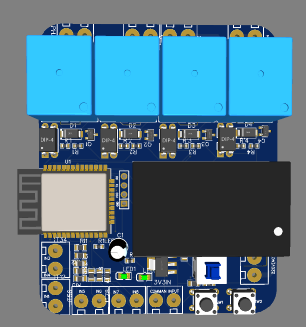
#define Switch1 34
#define Relay1 23
#define Switch2 35
#define Relay2 22
#define Switch3 32
#define Relay3 21
#define Switch4 33
#define Relay4 19
#define LED1 13
#define LED2 12
int MODE = 0;
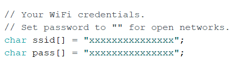
// Your WiFi credentials.
// Set password to "" for open networks.
char ssid[] = "XXXXXXXXXXXX";
char pass[] = "XXXXXXXXX";
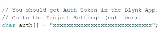
// You should get Auth Token in the Blynk App.
// Go to the Project Settings (nut icon).
char auth[] = " XXXXXXXXXXXXXXXXXXXXXXXXXXXXXXX";
int Flag1 = 0;
int Flag2 = 0;
int Flag3 = 0;
int Flag4 = 0;
BLYNK_WRITE(V1)
{
int pinValue = param.asInt(); // assigning incoming value from pin V1 to a variable
digitalWrite(Relay1, pinValue);
// process received value
}
BLYNK_WRITE(V2)
{
int pinValue = param.asInt(); // assigning incoming value from pin V2 to a variable
digitalWrite(Relay2, pinValue);
// process received value
}
BLYNK_WRITE(V3)
{
int pinValue = param.asInt(); // assigning incoming value from pin V3 to a variable
digitalWrite(Relay3, pinValue);
// process received value
}
BLYNK_WRITE(V4)
{
int pinValue = param.asInt(); // assigning incoming value from pin V4 to a variable
digitalWrite(Relay4, pinValue);
// process received value
}
void with_internet()
{
if (digitalRead(Switch1) == LOW)
{
if (Flag1 == 0 )
{
digitalWrite(Relay1, LOW);
if (DEBUG_SW) Serial.println("Relay1- ON");
Blynk.virtualWrite(V1, 0);
Flag1 = 1;
}
if (DEBUG_SW) Serial.println(" -ON");
}
if (digitalRead(Switch1) == HIGH )
{
if (Flag1 == 1)
{
digitalWrite(Relay1, HIGH);
if (DEBUG_SW) Serial.println("Relay1 OFF");
Blynk.virtualWrite(V1, 1);
Flag1 = 0;
}
if (DEBUG_SW)Serial.println(" OFF");
}
if (digitalRead(Switch2) == LOW)
{
if (Flag2 == 0 )
{
digitalWrite(Relay2, LOW);
if (DEBUG_SW) Serial.println("Relay2- ON");
Blynk.virtualWrite(V2, 0);
Flag2 = 1;
}
if (DEBUG_SW) Serial.println("Switch2 -ON");
}
if (digitalRead(Switch2) == HIGH )
{
if (Flag2 == 1)
{
digitalWrite(Relay2, HIGH);
if (DEBUG_SW) Serial.println("Relay2 OFF");
Blynk.virtualWrite(V2, 1);
Flag2 = 0;
}
if (DEBUG_SW)Serial.println("Switch2 OFF");
//delay(200);
}
if (digitalRead(Switch3) == LOW)
{
if (Flag3 == 0 )
{
digitalWrite(Relay3, LOW);
if (DEBUG_SW) Serial.println("Relay3- ON");
Blynk.virtualWrite(V3, 0);
Flag3 = 1;
}
if (DEBUG_SW) Serial.println("Switch3 -ON");
}
if (digitalRead(Switch3) == HIGH )
{
if (Flag3 == 1)
{
digitalWrite(Relay3, HIGH);
if (DEBUG_SW) Serial.println("Relay3 OFF");
Blynk.virtualWrite(V3, 1);
Flag3 = 0;
}
if (DEBUG_SW)Serial.println("Switch3 OFF");
//delay(200);
}
if (digitalRead(Switch4) == LOW)
{
if (Flag4 == 0 )
{
digitalWrite(Relay4, LOW);
if (DEBUG_SW) Serial.println("Relay4- ON");
Blynk.virtualWrite(V4, 0);
Flag4 = 1;
}
if (DEBUG_SW) Serial.println("Switch4 -ON");
}
if (digitalRead(Switch4) == HIGH )
{
if (Flag4 == 1)
{
digitalWrite(Relay4, HIGH);
if (DEBUG_SW) Serial.println("Relay4 OFF");
Blynk.virtualWrite(V4, 1);
Flag4 = 0;
}
if (DEBUG_SW)Serial.println("Switch4 OFF");
//delay(200);
}
}
void without_internet()
{
digitalWrite(Relay1, digitalRead(Switch1));
digitalWrite(Relay2, digitalRead(Switch2));
digitalWrite(Relay3, digitalRead(Switch3));
digitalWrite(Relay4, digitalRead(Switch4));
}
void checkBlynk() { // called every 3 seconds by SimpleTimer
bool isconnected = Blynk.connected();
if (isconnected == false) {
MODE = 1;
digitalWrite(LED1, HIGH);
digitalWrite(LED2, LOW);
}
if (isconnected == true) {
MODE = 0;
digitalWrite(LED1, HIGH);
digitalWrite(LED2, HIGH);
}
}
void setup()
{
// Debug console
if (DEBUG_SW) Serial.begin(9600);
pinMode(Switch1, INPUT);
pinMode(Relay1, OUTPUT);
pinMode(Switch2, INPUT);
pinMode(Relay2, OUTPUT);
pinMode(Switch3, INPUT);
pinMode(Relay3, OUTPUT);
pinMode(Switch4, INPUT);
pinMode(Relay4, OUTPUT);
pinMode(LED1, OUTPUT);
pinMode(LED2, OUTPUT);
digitalWrite(LED1, HIGH);
delay(200);
digitalWrite(LED2, HIGH);
delay(200);
digitalWrite(LED1, LOW);
digitalWrite(LED2, LOW);
delay(500);
digitalWrite(LED1, HIGH);
delay(200);
digitalWrite(LED2, HIGH);
delay(200);
digitalWrite(LED1, LOW);
digitalWrite(LED2, LOW);
//pinMode(MODE, INPUT);
WiFi.begin(ssid, pass);
timer.setInterval(3000L, checkBlynk); // check if connected to Blynk server every 3 seconds
Blynk.config(auth);//, ssid, pass);
}
void loop()
{
if (WiFi.status() != WL_CONNECTED)
{
if (DEBUG_SW) Serial.println("Not Connected");
}
else
{
if (DEBUG_SW) Serial.println(" Connected");
Blynk.run();
}
timer.run(); // Initiates SimpleTimer
if (MODE == 0)
with_internet();
else
without_internet();
}


")


I want to buy this project please let me know the price.
Rupee 2999/-
The post is written in very a good manner and it contains many useful information for me. https://yesmovies-yesmovies.store